DRV8301-Q1
SLOS842 –SEPTEMBER 2013
www.ti.com
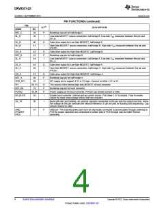
PIN FUNCTIONS (continued)
PIN
I/O(1)
DESCRIPTION
NAME
BST_C
SL_B
NO.
38
P
I
Bootstrap cap pin for half-bridge C
39
Low-Side MOSFET source connection, half-bridge B. Low-side VDS measured between this pin and
SH_B.
GL_B
SH_B
40
41
O
I
Gate drive output for Low-Side MOSFET, half-bridge B
High-Side MOSFET source connection, half-bridge B. High-side VDS measured between this pin and
PVDD1.
GH_B
BST_B
SL_A
42
43
44
O
P
I
Gate drive output for High-Side MOSFET, half-bridge B
Bootstrap cap pin for half-bridge B
Low-Side MOSFET source connection, half-bridge A. Low-side VDS measured between this pin and
SH_A.
GL_A
SH_A
45
46
O
I
Gate drive output for Low-Side MOSFET, half-bridge A
High-Side MOSFET source connection, half-bridge A. High-side VDS measured between this pin and
PVDD1.
GH_A
47
48
O
P
I
Gate drive output for High-Side MOSFET, half-bridge A
Bootstrap cap pin for half-bridge A
BST_A
VDD_SPI
PH
49
SPI supply pin to support 3.3V or 5V logic. Connect to either 3.3V or 5V.
The source of the internal high side MOSFET of buck converter
Bootstrap cap pin for buck converter
50, 51
52
O
P
P
I
BST_BK
PVDD2
EN_BUCK
53,54
55
Power supply pin for buck converter, PVDD2 cap should connect to GND.
Enable buck converter. Internal pull-up current source. Pull below 1.2V to disable. Float to enable.
Adjust the input undervoltage lockout with two resistors
SS_TR
56
57
I
Buck soft-start and tracking. An external capacitor connected to this pin sets the output rise time. Since
the voltage on this pin overrides the internal reference, it can be used for tracking and sequencing. Cap
should connect to GND
GND
(POWER
PAD)
P
GND pin. The exposed power pad must be electrically connected to ground plane through soldering to
PCB for proper operation and connected to bottom side of PCB through vias for better thermal
spreading.
4
Submit Documentation Feedback
Copyright © 2013, Texas Instruments Incorporated
Product Folder Links: DRV8301-Q1

 TI [ TEXAS INSTRUMENTS ]