4.0 Registers (Continued)
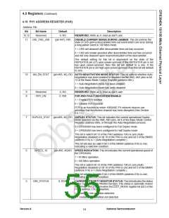
4.15 PHY ADDRESS REGISTER (PAR)
Address 19h
Bit
15:12
11
Bit Name
Reserved
Default
0, RO
Description
RESERVED: Write as 0, read as don't care.
DIS_CRS_JAB
(pin #47), RW
DISABLE CARRIER SENSE DURING JABBER: This bit controls the
state of CRS upon a descrambler time-out event which can occur during
a long jabber event in 100 Mb/s mode.
1 = CRS will deassert after descrambler time-out has occurred.
0 = CRS will remain asserted after descrambler time-out has occurred
and will only deassert upon resynchronization of the descrambler.
The default setting for this bit is dependent on the state of the
REPEATER pin (47) upon power-up/reset. If the REPEATER pin is set
low upon power-up/reset, then this bit will default to a one. If the
REPEATER pin is set high upon power-up/reset, then this bit will default
to zero.
10
AN_EN_STAT
(pin #95, 46), RO AUTO-NEGOTIATION MODE STATUS: This bit reflects whether Auto-
Negotiation has been enabled or disabled via the AN0, AN1 pins or bit
12 of the Basic Mode Control Register (address 00h.)
1 = Auto-Negotiation mode has been enabled
0 = Auto-Negotiation mode has been disabled
9
8
Reserved
FEFI_EN
0, RO
0, RW
RESERVED: Write as 0, read as don't care.
FAR END FAULT INDICATION ENABLE:
1 = Enable FEFI function
0 = Disable FEFI function
FEFI is an function by which 100BASE-FX network devices can
advertise that the receive channel has been disrupted (See Section
3.4.11.)
7
DUPLEX_STAT (pin #95, 46), RO DUPLEX STATUS: This bit indicates the current operational Duplex
mode selected via the AN0, AN1 pins, bit 8 of the Basic Mode Control
Register (address 00h), or through the Auto-Negotiation process.
1 = DP83840A has been configured to Full Duplex mode
0 = DP83840A has been configured to Half Duplex mode
This bit is valid if bit 10 of the PAR (address 19h) is zero (Auto-
Negotiation disabled) or bit 10 of the PAR is one and bit 5 of the BMSR
(address 01h) is 1 (Auto-Negotiation complete.)
This bit will also be valid if bit 2 of the BMSR (address 01h) is one,
indicating a valid link condition.
6
SPEED_10
(pin #95, 46)RO SPEED INDICATION: This bit indicates the current operational speed of
the DP83840A.
1 =10 Mb/s operation
0 =100 Mb/s operation
This bit is valid if bit 10 of the PAR (address 19h) is zero (Auto-
Negotiation disabled) or bit 10 of the PAR is one and bit 5 of the BMSR
(address 01h) is 1 (Auto-Negotiation complete.)
This bit will also be valid if bit 2 of the BMSR (address 01h) is one,
indicating a valid link condition.
5
CIM_STATUS
0, RO/L
CARRIER INTEGRITY MONITOR STATUS: This bit indicates the status
of the Carrier Integrity Monitor function. This status is optionally muxed
out through the LED1 pin when the LED1_MODE register bit (bit 2 of the
PCR, address 17h) is asserted.
1 = Unstable link condition detected
0 = Unstable link condition not detected
Version A
National Semiconductor
54

 TI [ TEXAS INSTRUMENTS ]