4.0 Registers (Continued)
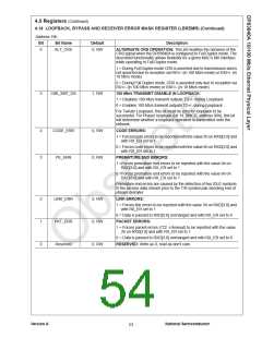
4.14 LOOPBACK, BYPASS AND RECEIVER ERROR MASK REGISTER (LBREMR) (Continued)
Address 18h
Bit
Bit Name
Default
Description
6
ALT_CRS
0, RW
ALTERNATE CRS OPERATION: This bit modifies the behavior of the
CRS signal when the DP83840A is configured to Full Duplex mode. The
described functionality allows flexibility for a given MAC’s MII interface
while operating in Full Duplex mode.
1 = During Full Duplex mode CRS is asserted due to transmission and is
not asserted due to reception via RD+/- (in 100 Mb/s mode) or RXI+/- (in
10 Mb/s mode)
0 = During Full Duplex mode, CRS is asserted only due to reception via
RD+/- (in 100 Mb/s mode) or RXI+/- (in 10 Mb/s mode)
5
LBK_XMT_DS
1, RW
100 Mb/s TRANSMIT DISABLE IN LOOPBACK:
1 = Disables 100 Mb/s transmit outputs TD+/- during Loopback
0 = Enables 100 Mb/s transmit outputs TD+/- during Loopback
For Twister Loopback, this bit must be zero for loopback to be
successful. For Phaser loopback (bit 14, BMCR, address 00h), this bit
will determine whether a loopback operation is transmitted onto the
network.
4
3
CODE_ERR
PE_ERR
0, RW
0, RW
CODE ERRORS:
1 = Forces code errors to be reported with the value 5h on RXD[3:0] and
with RX_ER set to 1
0 = Forces code errors to be reported with the value 6h on RXD[3:0] and
with RX_ER set to 1
PREMATURE END ERRORS:
1 =Forces premature end errors to be reported with the value 4h on
RXD[3:0] and with RX_ER set to 1
0 =Forces premature end errors to be reported with the value 6h on
RXD[3:0] and with RX_ER set to 1
Premature end errors are caused by the detection of two IDLE symbols
in the receive data stream prior to the T/R symbol pair denoting end of
stream delimiter.
2
1
0
LINK_ERR
PKT_ERR
Reserved
0, RW
0, RW
0, RW
LINK ERRORS:
1 = Forces link errors to be reported with the value 3h on RXD[3:0] and
with RX_ER set to 1
0 = Data is passed to RXD[3:0] unchanged and with RX_ER set to 0
PACKET ERRORS:
1 = Forces packet errors (722 s timeout) to be reported with the value
2h on RXD[3:0] and with RX_ER set to 1
0 = Data is passed to RXD[3:0] unchanged and with RX_ER set to 0
RESERVED: Write as 0, read as don't care.
Version A
National Semiconductor
53

 TI [ TEXAS INSTRUMENTS ]