4.0 Registers (Continued)
4.13 PCS CONFIGURATION REGISTER (PCR) (Continued)
Address 17h
Bit
Bit Name
Default
Description
11
ENCSEL
0, RW
ENCODER MODE SELECT:
1 = External transceiver binary encoding
0 = External transceiver MLT3 encoding
This bit drives the DP83840A's ENCSEL signal (pin 53). ENCSEL should
be connected to the ENCSEL input of a DP83223 Twister.
10:8
7
Reserved
X, RO
0, RW
RESERVED: Write as 0, read as don’t care.
CLK25M DISABLE:
CLK25MDIS
1 = CLK25M output clock signal (pin 81) tri-stated
0 = CLK25M enable
This helps reduce ground bounce and power consumption should this
output not be required. For applications requiring the CLK25M output,
leave this bit set to 0. See Section 3.5 for more details.
6
5
F_LINK_100
CIM _DIS
1, RW
FORCE GOOD LINK IN 100 Mb/s:
1 = Normal 100 Mb/s operation
0 = Force 100 Mb/s Good Link status
This forces good link and will assert the LINK LED. This bit is useful for
diagnostic purposes.
(pin #47), RW
CARRIER INTEGRITY MONITOR DISABLE:
1 = Carrier Integrity Monitor function disabled (Node/Switch operation)
0 = Carrier Integrity Monitor function enabled (Repeater operation)
The REPEATER pin (pin # 47) determines the default state of this bit to
automatically enable or disable the CIM function as required for IEEE
802.3 compliant applications. After power-on/hardware reset, software
may enable or disable this function independent of repeater or node/
switch mode.
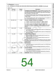
4
TX_OFF
0, RW
FORCE TRANSMIT OFF:
1 = 100 Mb/s outputs TD+/- inactive regardless of signalling on the MII
interface.
0 = 100 Mb/s transmission outputs TD +/- enabled
This will inhibit normal 100 Mb/s network activity and is provided only for
test flexibility.
3
2
Reserved
X, RO
0, RW
RESERVED: Write as 0, read as don't care.
LED1_MODE
LED1 MODE SELECT:
1 = LED1 output (pin 42) configured to indicate connection status
(CON_STATUS, bit 5 of the PAR, address 19h). This is useful for
network management purposes in 100BASE-TX mode.
0 = Normal LED1 operation--10 Mb/s and 100 Mb/s transmission activity
1
0
LED4_MODE
Reserved
0, RW
X, RO
LED4 MODE SELECT:
1 = LED4 output (pin 37) configured to indicate Full Duplex mode status
for 10 Mb/s and 100 Mb/s operation
0 = LED4 output configured to indicate Polarity in 10BASE-T mode or
Full Duplex in 100BASE-TX mode
RESERVED: Write as 0, read as don't care.
Version A
National Semiconductor
51

 TI [ TEXAS INSTRUMENTS ]