4.0 Registers (Continued)
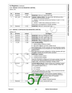
4.16 10BASE-T STATUS REGISTER (10BTSR)
Address 1Bh
Bit
15:10
9
Bit Name
Reserved
10BT_SER
Default
0, RO
Description
RESERVED: Write as 0, read as don't care.
(Pin #98), RW
10BASE-T SERIAL MODE: The value on the 10BTSER pin (98) is
latched into this bit at power-up/reset.
1 = 10BASE-T serial mode selected (see Sections 2.5 and 3.1.3.3 for
more details)
0 = 10BASE-T nibble mode selected (see Section 3.1.3.2)
Serial mode is not supported for 100 Mb/s operation.
RESERVED: Write as 0, read as don't care.
8:0
Reserved
0, RO
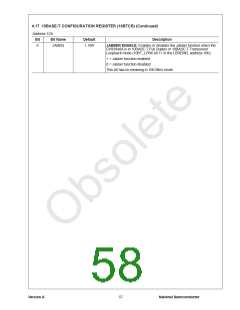
4.17 10BASE-T CONFIGURATION REGISTER (10BTCR)
Address 1Ch
Bit
15
14:8
7
Bit Name
Reserved
Reserved
Reserved
Reserved
LP_EN
Default
1, RW
X, RO
1, RW
X, RO
1, RW
Description
RESERVED: Write as 1, read as don't care.
RESERVED: Write as 0, read as don't care.
RESERVED: Write as 1, read as don't care.
RESERVED: Write as 0, read as don't care.
LINK PULSE ENABLE:
6
5
1 = Transmission of link pulses enabled
0 = Link pulses disabled, good link condition forced
When configured for 100 Mb/s operation with Auto-Negotiation enabled,
clearing this bit will force the DP83840A into 10 Mb/s operation with link
pulses disabled.
If the DP83840A has been configured for 100 Mb/s operation with Auto-
Negotiation disabled, this bit will not affect operation.
4
3
HBE
1, RW
1, RW
HEARTBEAT ENABLE:
1 = Heartbeat function enabled
0 = Heartbeat function disabled
When the DP83840A is configured for Full Duplex operation, this bit will
be ignored (the collision/heartbeat function has no meaning in Full
Duplex mode). This bit has no meaning in 100 Mb/s mode.
UTP/STP
UTP/STP MEDIA SELECT: Selects between the Unshielded Twisted
Pair (UTP) transmit outputs (TXU+/-) and the Shielded Twisted Pair
(STP) transmit outputs (TXS+/-).
1 = UTP selected
0 = STP selected
Only one output pair (TXU+/- or TXS+/-) may be selected at one time.
The pair that is not selected will tri-state.
2
1
LSS
0, RW
0, RO
LOW SQUELCH SELECT: Selects between standard 10BASE-T
receiver squelch threshold and a reduced squelch threshold that is
useful for longer cable applications and/or STP operation.
1 = Low Squelch Threshold selected
0 = Normal 10BASE-T Squelch Threshold selected
RESERVED: Write as 0, read as don't care.
Reserved
Version A
National Semiconductor
56

 TI [ TEXAS INSTRUMENTS ]