DM385, DM388
www.ti.com
SPRS821D –MARCH 2013–REVISED DECEMBER 2013
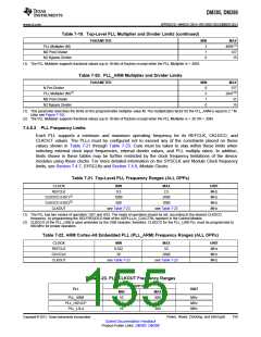
Table 7-19. Top-Level PLL Multiplier and Divider Limits (continued)
PARAMETER
MIN
2
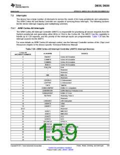
MAX
4095(1)
127
PLL Multiplier (M)
M2 Post Divider
N2 Bypass Divider
1
0
15
(1) The PLL Multiplier supports fractional values (up to 18-bits of fraction) except when the PLL Multiplier is > 4093.
Table 7-20. PLL_ARM Multiplier and Divider Limits
PARAMETER
MIN
0
MAX
127
N Pre-Divider
PLL Multiplier (M)(1)
2
2047(2)
M2 Post Divider
1
31
N2 Bypass Divider
0
15
(1) This parameter describes the limits on the programmable multiplier value M. The multiplication factor for the PLL_ARM is equal to 2 * M
(also see Figure 7-18).
(2) The PLL Multiplier supports fractional values (up to 18-bits of fraction) except when the PLL Multiplier is < 20 OR > 2045.
7.4.6.3 PLL Frequency Limits
Each PLL supports a minimum and maximum operating frequency for its REFCLK, CKLDCO, and
CLKOUT values. The PLLs must be configured not to exceed any of the constraints placed on these
values shown in Table 7-21 through Table 7-23. Care must be taken to stay within these limits when
selecting external clock input frequencies, internal divider values, and PLL multiply ratios. In addition,
limits shown in these tables may be further restricted by the clock frequency limitations of the device
modules using these clocks. For more detailed information on the SYSCLK and Module Clock frequency
limits, see Section 7.4.7, SYSCLKs and Section 7.4.8, Module Clocks.
Table 7-21. Top-Level PLL Frequency Ranges (ALL OPPs)
CLOCK
REFCLK
CLKDCO (HS1)(1)
CLKDCO (HS2)(2)
CLKOUT
MIN
0.5
MAX
2.5
UNIT
MHz
MHz
MHz
MHz
1000
2000
500
1000
see Table 7-23
see Table 7-23
(1) The PLL has two modes of operation: HS1 and HS2. The mode of operation should be set, according to the desired CLKDCO
frequency, by programming the SELFREQDCO field of the ADPLLLJx_CLKCTRL registers in the Control Module.
(2) CLKDCO of the PLL_USB is used undivided by the USB modules; therefore, CLKDCO for the PLL_USB PLL must be programmed to
960 MHz for proper operation.
Table 7-22. ARM Cortex-A8 Embedded PLL (PLL_ARM) Frequency Ranges (ALL OPPs)
CLOCK
REFCLK
DCOCLK
CLKOUT
MIN
0.032
MAX
52
UNIT
MHz
MHz
MHz
20
2000
see Table 7-23
see Table 7-23
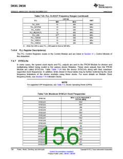
Table 7-23. PLL CLKOUT Frequency Ranges
OPP100
PLL
UNIT
MIN
10
MAX
600
266
200
PLL_ARM
PLL_HDVICP
PLL_L3L4
MHz
MHz
MHz
10
10
Copyright © 2013, Texas Instruments Incorporated
Power, Reset, Clocking, and Interrupts
155
Submit Documentation Feedback
Product Folder Links: DM385 DM388

 TI [ TEXAS INSTRUMENTS ]