DM385, DM388
www.ti.com
SPRS821D –MARCH 2013–REVISED DECEMBER 2013
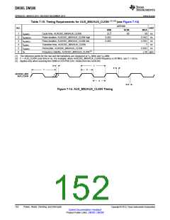
Table 7-16. Timing Requirements for CLKIN32 (1)(2) (see Figure 7-15)
OPP100
NOM
NO.
UNIT
MIN
1/32768
0.45C
MAX
1
2
3
4
5
tc(CLKIN32)
Cycle time, CLKIN32
s
tw(CLKIN32H)
tw(CKIN32L)
tt(CLKIN32)
tJ(CLKIN32)
Pulse duration, CLKIN32 high
Pulse duration, CLKIN32 low
Transition time, CLKIN32
Period jitter, CLKIN32
0.55C
0.55C
7
ns
ns
ns
ns
0.45C
0.02C
(1) The reference points for the rise and fall transitions are measured at VIL MAX and VIH MIN.
(2) C = CLKIN32 cycle time in ns. For example, when CLKIN32 frequency is 32768 Hz, use C = 1/32768 s.
5
1
4
1
2
CLKIN32
3
4
Figure 7-15. CLKIN32 Timing
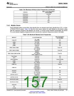
Table 7-17. Switching Characteristics Over Recommended Operating Conditions for CLKOUTx (CLKOUT0
and CLKOUT1)(1) (2)
(see Figure 7-16)
OPP100
NO.
PARAMETER
UNIT
MIN
5
MAX
1
2
3
4
tc(CLKOUTx)
tw(CLKOUTxH)
tw(CLKOUTxL)
tt(CLKOUTx)
Cycle time, CLKOUTx
ns
ns
ns
ns
Pulse duration, CLKOUTx high
Pulse duration, CLKOUTx low
Transition time, CLKOUTx
0.45P
0.45P
0.55P
0.55P
0.05P
(1) The reference points for the rise and fall transitions are measured at VOL MAX and VOH MIN.
(2) P = 1/CLKOUTx clock frequency in nanoseconds (ns). For example, when CLKOUTx frequency is 200 MHz, use P = 5 ns.
2
4
1
CLKOUTx
(Divide-by-1)
3
4
Figure 7-16. CLKOUTx Timing
Copyright © 2013, Texas Instruments Incorporated
Power, Reset, Clocking, and Interrupts
153
Submit Documentation Feedback
Product Folder Links: DM385 DM388

 TI [ TEXAS INSTRUMENTS ]