DLPA2000
www.ti.com.cn
ZHCSCO5B –JUNE 2014–REVISED FEBRUARY 2018
VINA
Hysteresis
BAT_LOW Threshold
Hysteresis
UVLO Threshold
ACTIVE
BAT LOW
(Internal Signal)
INACTIVE
ACTIVE
200-µs
deglitch
UVLO
INACTIVE
(Internal Signal)
Programmable Deglitch Time1
A. This time is programmable from 0 to 100 µs.
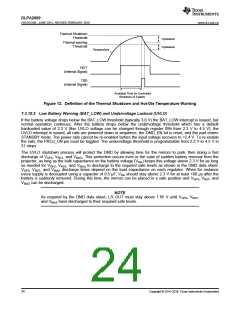
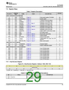
Figure 13. UVLO is Asserted When the Input Supply Drops Below the UVLO Threshold
7.3.10.3 DMD Regulator Fault (DMD_FLT)
The DMD regulator is continuously monitored to check if the output rails are in regulation and if the inductor
current increases as expected during a switching cycle. If either one of the output rails drops out of regulation (for
example, due to a shorted output) or the inductor current does not increase as expected during a switching cycle
(due to a disconnected inductor), the DMD_FLT interrupt bit is set in the INT register, the DMD_EN bit is reset,
and the DMD regulator is shut down. Resetting the DMD_EN bit also causes the LED driver to power down. To
restart the system, the PROJ_ON pin must be toggled. In case the interrupt is masked, it is sufficient to set the
DMD_EN bit to restart the system.
7.3.10.4 V6V Power-Good (V6V_PGF) Fault
The LED driver regulation loop requires the V6V rail for proper operation. The rail is continuously monitored and
should the output drop below the power-good threshold, the V6V_PGF bit is set. The VLED buck-boost is then
disabled and attempts to restart automatically.
7.3.10.5 VLED Overvoltage (VLED_OVP) Fault
If the buck-boost output voltage rises above 5.4 V, the VLED_OVP interrupt is set but the buck-boost regulator is
not turned off. A typical condition to cause this fault is an open LED.
7.3.10.6 VLED Power Save Mode
In normal PWM operation, the efficiency of the VLED buck-boost converter dramatically reduces for LED currents
below 100 mA. In this case, the power save mode allows high converting efficiency at low output currents by
skipping pulses in the switcher’s gate driver control.
7.3.10.7 V1V8 PG Failure
If for any reason the voltage on the LS_OUT drops below approximately 1.3 V, then VOFS, VBIAS, and VRST
immediately go into fast shut down. Holding off power down to do mirror parking is not included since 1.3 V is too
low to wait for this. Reactivating can only be done by toggling the PROJ_ON off and on again.
7.3.10.8 Interrupt Pin (INTZ)
The interrupt pin is used to signal events and fault conditions to the host processor. Whenever a fault or event
occurs in the IC, the corresponding interrupt bit is set in the INT register, and the open-drain output is pulled low.
The INTZ pin is released (returns to HiZ state) and fault bits are cleared when the INT register is read by the
host.
However, if a failure persists, the corresponding INT bit remains set and the INTZ pin is pulled low again after a
maximum of 32 µs.
Copyright © 2014–2018, Texas Instruments Incorporated
25

 TI [ TEXAS INSTRUMENTS ]