DLPA2000
www.ti.com.cn
ZHCSCO5B –JUNE 2014–REVISED FEBRUARY 2018
VLED
BUCK-BOOST
VLED
FB
SW4LIM_EN
SW4
I-LED
0
ILIM [3:0]
VDAC
E/A
1
SW5LIM_EN
SW5
I-LED
0
E/A
1
SW6LIM_EN
SW6
I-LED
0
LED_SEL [1:0]
MAP
STROBE
DECODER
RLIM
E/A
1
SW4_IDAQ [9:0]
RLIM_K
SW5_IDAQ [9:0]
SW6_IDAQ [9:0]
IDAC
I-DAC
200
RLIM
RBOT_K
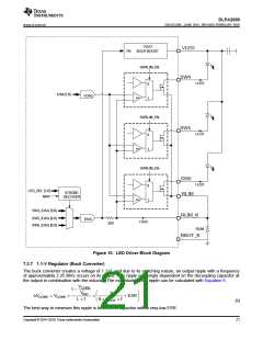
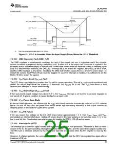
Figure 10. LED Driver Block Diagram
7.3.7 1.1-V Regulator (Buck Converter)
The buck converter creates a voltage of 1.1 V, and due to its switching nature, an output ripple with a frequency
of approximately 2.25 MHz occurs on its output. This ripple is strongly dependent on the decoupling capacitor at
the output in combination with the inductor. The magnitude of the ripple can be calculated with Equation 6.
VCORE
1 -
≈
∆
«
’
÷
◊
V
1
INC
DVCORE = VCORE
ì
ì
+ ESR
L ì f
8 ì COUT ì f
(6)
21
The best way to minimize this ripple is to select a capacitor with a very-low ESR.
Copyright © 2014–2018, Texas Instruments Incorporated

 TI [ TEXAS INSTRUMENTS ]