DLPA2000
www.ti.com.cn
ZHCSCO5B –JUNE 2014–REVISED FEBRUARY 2018
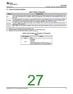
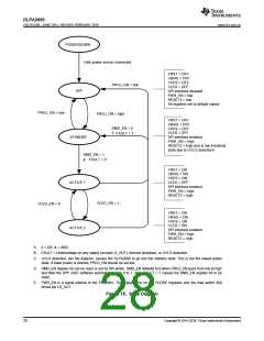
7.4 Device Functional Modes
Table 5. Modes of Operation
MODE
DESCRIPTION
This is the lowest-power mode of operation. All power functions are turned off, registers are reset to their default values, and
the IC does not respond to SPI commands. RESETZ pin is pulled low. The IC will enter OFF mode whenever the PROJ_ON
pin is low.
OFF
The DMD regulators and LED power (VLED) are turned off, but the IC does respond to the SPI. The device enters STANDBY
mode whenever PROJ_ON is set high or DMD_EN(1) bit is set to 0 using the SPI interface after PROJ_ON is already high.
The device also enters STANDBY mode when a fault condition is detected(2). (See Protection Circuits).
STANDBY
The DMD supplies are enabled but LED power (VLED) is disabled. PROJ_ON pin must be high, DMD_EN bit must be set to 1,
and VLED_EN(3) bit is set to 0.
ACTIVE1
ACTIVE2
DMD supplies and LED power are enabled. PROJ_ON pin must be high and DMD_EN and VLED_EN bits must both be set to
1.
(1) Settings can be done through Reg01h [9] and Reg2E [119].
(2) Power-good faults, over-voltage, overtemperature shutdown, and undervoltage lockout.
(3) Settings can be done through Reg47h [60], bit is named VLED_EN_SET
.
Table 6. Device State as a Function of Control-Pin
Status
PROJ_ON PIN
STATE
LOW
OFF
STANDBY
ACTIVE1
ACTIVE2
HIGH
(Device state depends on DMD_EN and VLED_EN
bits and whether there are any fault conditions.)
Copyright © 2014–2018, Texas Instruments Incorporated
27

 TI [ TEXAS INSTRUMENTS ]