DLPA2000
ZHCSCO5B –JUNE 2014–REVISED FEBRUARY 2018
www.ti.com.cn
7.3.8 Motor Driver
Two control modes are available in the DLPA2000: IN/IN mode and PHASE/ENABLE mode. IN/IN mode is
selected if the MODE pin is driven low or left unconnected; PHASE/ENABLE mode is selected if the MODE pin is
driven to logic high. Table 2 and Table 3 show the logic for these modes.
The main difference between both modes is that to change the rotation direction for IN/IN mode, both xIN1 and
xIN2 signals must change polarity, while for PHASE/ENABLE mode, the PHASE signal must be held high while
the PHASE signal is used to change rotation direction for a DC motor. In case a stepper motor is used, the
sequence of OUT1 and OUT2 determines the rotation direction.
The motor position is changed by using the internal, register-generated, control signals AIN1 and AIN2 (register
0F[123:122] in combination with BIN1 and BIN2 (register 0F[121:120].
Table 2. IN/IN Mode (See Figure 31)
MD_MODE
BIT 124 REG 0Fh
FUNCTION
(DC MOTOR)
xIN1
xIN2
xOUT1
xOUT2
0
0
0
0
0
0
1
1
0
1
0
1
Z
L
Z
H
L
Coast
Reverse
Forward
Brake
H
L
L
Table 3. PHASE/ENABLE Mode (See Figure 31)
MD_MODE
BIT 124 REG 0Fh
xIN1
(ENABLE)
xIN2
(PHASE)
FUNCTION
(DC MOTOR)
xOUT1
xOUT2
1
1
1
0
1
1
X
1
0
L
L
L
H
L
Brake
Reverse
Forward
H
7.3.8.1 Motor Driver Overcurrent Protection
An analog current limit circuit on each FET limits the current through the FET by removing the gate drive. If this
analog current limit persists for a longer period of time than the overcurrent deglitch time, all FETs in the H-
bridge will be disabled. After approximately 1 ms, the bridge will be re-enabled automatically.
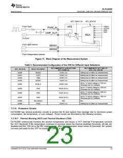
7.3.9 Measurement System
The measurement system is composed of a 10:1 analog multiplexer (MUX), a programmable-gain amplifier, and
a comparator. It works together with the DPP processor to provide:
•
White-point correction (WPC) by independently adjusting the RGB LED currents after measuring the
brightness of each color with an external light sensor
•
A measurement of the:
–
–
–
–
Battery voltage
LED forward voltage
Exact LED current
Temperature as derived by measuring the voltage across an external thermistor
Figure 11 shows a block diagram of the measurement system.
22
Copyright © 2014–2018, Texas Instruments Incorporated

 TI [ TEXAS INSTRUMENTS ]