DLPA2000
ZHCSCO5B –JUNE 2014–REVISED FEBRUARY 2018
www.ti.com.cn
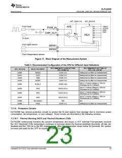
Thermal Shutdown
Threshold
Hysteresis
Hysteresis
Thermal warning
Threshold
Temperature
HOT
(Internal Signal)
TSD
(Internal Signal)
Available Time for Controlled
Shutdown of System
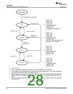
Figure 12. Definition of the Thermal Shutdown and Hot-Die Temperature Warning
7.3.10.2 Low Battery Warning (BAT_LOW) and Undervoltage Lockout (UVLO)
If the battery voltage drops below the BAT_LOW threshold (typically 3.0 V) the BAT_LOW interrupt is issued, but
normal operation continues. After the battery drops below the undervoltage threshold which has a default
hardcoded value of 2.3 V (this UVLO voltage can be changed through register 09h from 2.3 V to 4.5 V), the
UVLO interrupt is issued, all rails are powered down in sequence, the DMD_EN bit is reset, and the part enters
STANDBY mode. The power rails cannot be re-enabled before the input voltage recovers to >2.4 V. To re-enable
the rails, the PROJ_ON pin must be toggled. The undervoltage threshold is programmable from 2.3 V to 4.5 V in
31 steps.
The UVLO shutdown process will protect the DMD by allowing time for the mirrors to park, then doing a fast
discharge of VOFS, VRST, and VBIAS. This protection occurs even in the case of sudden battery removal from the
projector, as long as the bulk capacitance on the battery voltage (VINx) keeps this voltage above 2.3 V for as long
as needed for VOFS, VRST, and VBIAS to discharge to the required safe levels as shown in the DMD data sheet.
VOFS, VRST, and VBIAS discharge times depend on the load capacitance on each regulator. When for instance
every supply is decoupled using a capacitor of 0.5 µF, VINx should stay above 2.3 V for at least 100 µs after the
battery is suddenly removed. During this time, the mirrors can be placed in a safe position and VOFS, VRST, and
VBIAS can be discharged.
NOTE
As required by the DMD data sheet, LS_OUT must stay above 1.65 V until VOFS, VRST
,
and VBIAS have discharged to their required safe levels.
24
Copyright © 2014–2018, Texas Instruments Incorporated

 TI [ TEXAS INSTRUMENTS ]