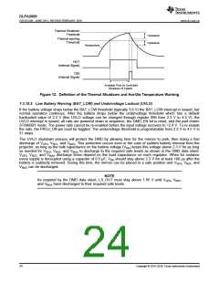
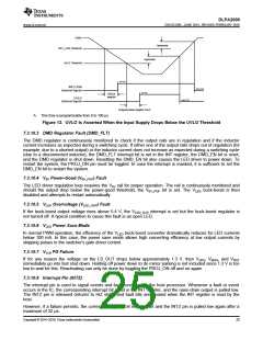
DLPA2000
ZHCSCO5B –JUNE 2014–REVISED FEBRUARY 2018
www.ti.com.cn
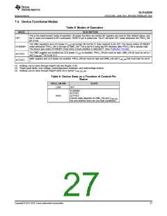
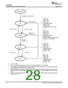
POWERDOWN
Valid power source connected
VRST = OFF
VBIAS = OFF
VOFS = OFF
VLED = OFF
PROJ_ON = low
OFF
SPI interface disabled
PWR_EN = low
RESETZ = low
All registers set to default values
PROJ_ON = low
PROJ_ON = high
VRST = OFF
VBIAS = OFF
VOFS = OFF
DMD_EN = 0
||
VLED = OFF
FAULT = 1
STANDBY
SPI interface enabled
PWR_EN = high
RESETZ = high (but is low if entered
state due to UVLO detection)
DMD_EN = 1
FAULT = 0
&
VRST = ON
VBIAS = ON
VOFS = ON
ACTIVE 1
VLED = OFF
SPI interface enabled
PWR_EN = high
RESETZ = high
VLED_EN = 1
VLED_EN = 0
VRST = ON
VBIAS = ON
VOFS = ON
VLED = ON
ACTIVE 2
SPI interface enabled
PWR_EN = high
RESETZ = high
A. || = OR, & = AND.
B. FAULT = Undervoltage on any supply (except LS_OUT), thermal shutdown, or UVLO detection.
C. UVLO detection, per the diagram, causes the DLPA2000 to go into the standby state. This is not the lowest power
state. If lower power is desired, PROJ_ON should be set low.
D. DMD_EN register bit can be reset or set by SPI writes. DMD_EN defaults to 0 when PROJ_ON goes from low to high
and then the DPP ASIC software automatically sets it to 1. Also, FAULT = 1 causes the DMD_EN register bit to be
reset.
E. PWR_EN is a signal internal to the PAD200x. This signal turns on the VCORE regulator and the load switch that
drives pin LS_OUT.
Figure 15. State Diagram
28
Copyright © 2014–2018, Texas Instruments Incorporated

 TI [ TEXAS INSTRUMENTS ]