bq76925
SLUSAM9A –JULY 2011–REVISED JULY 2011
www.ti.com
UNIT
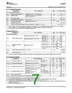
Current Sense Amplifier
PARAMETER
TEST CONDITION
MIN
TYP
4
MAX
I_GAIN = 0
I_GAIN = 1
Measured from SENSEN,
SENSEP to VIOUT
GVIOUT Current sense amplifier gain
8
Measured from SENSEN,
SENSEP to VSS
VIIN
Current sense amp input range
Current sense amp output range
–125
375
mV
REF_SEL = 0
REF_SEL = 1
REF_SEL = 0
REF_SEL = 1
0.25
0.5
1.25
2.5
V
V
V
V
Measured at VIOUT
VIOUT
1.0
2.0
Measured at VIOUT
SENSEP = SENSEN
Zero current output
∆VIOUT Current amplifier accuracy
–1%
1%
10
(1)
IVIOUT
VIOUT output current
µA
(1) Max DC load for specified accuracy
Over Current Comparator
PARAMETER
TEST CONDITION
MIN
TYP
MAX UNIT
VBAT_COMP
GVCOMP
VITRIP
Minimum VBAT for comparator operation(1)
5
V
Measured from SENSEP to comparator
input
Comparator amplifier gain
1
Current comparator trip threshold(2)
25
–6
400
6
mV
mV
V
VITRIP = 25 mV
∆VITRIP
Current comparator accuracy
ALERT Output Low Logic
VITRIP > 25 mV
–10%
10%
0.4
NA
VOL_ALERT
VOH_ALERT
IALERT
IALERT = 1 mA
V
(3)
ALERT Output High Logic
NA
1
NA
ALERT Pulldown current
ALERT Leakage current
Comparator response time
ALERT = 0.4 V, Output driving low
ALERT = 5.0 V, Output high-Z
mA
μA
µs
IALERT_LKG
tOC
< 1
100
(1) The Over Current Comparator is not guaranteed to work when VBAT is below this voltage.
(2) Trip threshold selectable from 25, 50, 75, 100, 125, 150, 175, 200, 225, 250, 275, 300, 325, 350, 375 or 400 mV
(3) This parameter NA because output is open drain.
Internal Temperature Measurement
PARAMETER
TEST CONDITION
MIN
TYP
1.2
MAX UNIT
VTEMP_INT
Internal temperature voltage
Internal temperature voltage sensitivity
Measured at VCOUT, TINT = 25°C
1.15
1.25
V
∆VTEMP_INT
–4.4
mV /
ºC
Cell Balancing and Open Cell Detection
PARAMETER
TEST CONDITION
MIN
TYP
MAX UNIT
RDS,ON for VC1 internal FET switch,
VCn = 3.6 V
1
3
5
RBAL
Cell balancing internal resistance(1)
Ω
RDS,ON for internal VC2 to VC6 FET switch,
VCn = 3.6 V
3
5.5
8
(1) Balancing current is not internally limited. The cell balancing operation is completely controlled by the Host processor, no automatic
function or time-out is included in the part. Care must be used to ensure that balancing current through the part is below the maximum
power dissipation limit. The Host algorithm is responsible for limiting thermal dissipation to package ratings.
8
Copyright © 2011, Texas Instruments Incorporated

 TI [ TEXAS INSTRUMENTS ]