bq76925
SLUSAM9A –JULY 2011–REVISED JULY 2011
www.ti.com
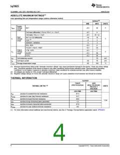
ABSOLUTE MAXIMUM RATINGS(1)
over operating free-air temperature range (unless otherwise noted)
RANGE(2)
MAX
MIN
UNITS
Supply
VBAT
voltage
range
BAT
–0.3
36
V
Cell input differential, VCn to VCn+1, n = 0 to 5
Cell input, VCn, n = 1 to 6
–0.3
–0.3
–10
–3
9
(6 × n)
10
3
Input
BAT to VC6 differential
VI
voltage
range
V
(3)
VC0
SENSEP, SENSEN
SCL, SDA
–3
3
–0.3
–0.3
–0.3
–0.3
–0.3
6
VCOUT, VIOUT, VREF
VTB, V3P3
3.6
7
Output
voltage
range
VO
V
ALERT
30
36
70
70
150
VCTL
ICB
Cell balancing current
Cell input current
mA
mA
°C
IIN
–25
–65
TSTG
Storage temperature range
(1) Stresses beyond those listed under “absolute maximum ratings” may cause permanent damage to the device. These are stress ratings
only. Functional operation of the device at these or any other conditions beyond those indicated under “Recommended Operating
Conditions” is not implied. Exposure to absolute–maximum–rated conditions for extended periods may affect device reliability.
(2) All voltages are relative to VSS, except “Cell input differential”.
(3) Negative voltage swings on VC0 in the absolute maximum range can cause unwanted circuit behavior and should be avoided.
THERMAL INFORMATION
bq76925
TSSOP
QFN
(PW PACKAGE)
(RGE PACKAGE)
PRODUCT
THERMAL METRIC(1)
UNITS
PREVIEW
(20) PINS
97.5
31.7
48.4
1.5
(24) PINS
θJA
Junction-to-ambient thermal resistance
Junction-to-case (top) thermal resistance
Junction-to-board thermal resistance
θJCtop
θJB
°C/W
ψJT
Junction-to-top characterization parameter
Junction-to-board characterization parameter
Junction-to-case (bottom) thermal resistance
ψJB
47.9
n/a
θJCbot
(1) For more information about traditional and new thermal metrics, see the IC Package Thermal Metrics application report, SPRA953.
4
Copyright © 2011, Texas Instruments Incorporated

 TI [ TEXAS INSTRUMENTS ]