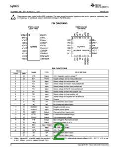
bq76925
SLUSAM9A –JULY 2011–REVISED JULY 2011
www.ti.com
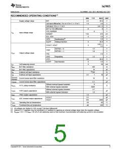
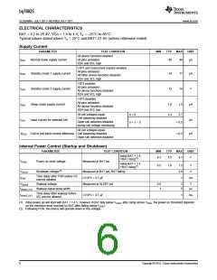
ELECTRICAL CHARACTERISTICS
BAT = 4.2 to 26.4V, VCn = 1.4 to 4.4, TA = –25°C to 85°C
Typical values stated where TA = 25°C and BAT= 21.6V (unless otherwise noted)
Supply Current
PARAMETER
TEST CONDITION
All device functions enabled
MIN
TYP
MAX
UNIT
IDD1
Normal mode supply current
All pins unloaded
40
48
µA
SDA and SCL high
V3P3 and overcurrent monitor enabled
All pins unloaded
All other device functions disabled
SDA and SCL high
IDD2
Standby mode 1 supply current
Standby mode 2 supply current
Sleep mode supply current
14
12
17
14
µA
V
V3P3 enabled
All pins unloaded
All device functions disabled
SDA and SCL high
IDD3
IDD4
IVCn
V3P3 disabled
All pins unloaded
All device functions disabled
SDA and SCL low
1.0
2.4
1.5
µA
All cell voltages equal
Cell balancing disabled
Open cell detection disabled
during cell voltage monitoring
n = 6
2.7
Input current for selected cell
µA
µA
n = 1 – 5
< 0.5
All cell voltages equal
∆IVCn Cell to cell input current difference Cell balancing disabled
< 0.2
Open cell detection disabled
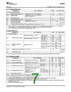
Internal Power Control (Startup and Shutdown)
PARAMETER
TEST CONDITION
MIN
TYP
MAX
UNIT
Initial BAT < 1.4
4.3
4.5
4.7
V
VBAT rising(1)
VPOR
Power on reset voltage
Shutdown voltage(2)
Measured at BAT pin
Initial BAT > 1.4
6.5
7.0
7.5
3.6
1
V
V
VBAT rising(1)
VSHUT
tPOR
Measured at BAT pin, BAT falling
Time delay after POR before I2C
comms allowed
CV3P3 = 4.7 µF
ms
VWAKE
Wakeup voltage
Measured at ALERT pin
0.8
1
2
5
V
tWAKE_PLS Wakeup signal pulse width
μs
Time delay after wakeup before
tWAKE_DLY
CV3P3 = 4.7 µF
1
ms
I2C comms allowed
(1) Initial power up will start with BAT < 1.4 V, however if BAT falls below VSHUT after rising above VPOR, the power on threshold depends
on the minimum level reached by BAT after falling below VSHUT
(2) Following POR, the device will operate down to this voltage.
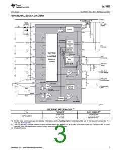
6
Copyright © 2011, Texas Instruments Incorporated

 TI [ TEXAS INSTRUMENTS ]