bq76925
www.ti.com
SLUSAM9A –JULY 2011–REVISED JULY 2011
POWER MODES
Power On Reset (POR)
When initially powering up the bq76925, the voltage on the BAT pin must exceed VPOR (4.7 V max) before the
device will turn on. Following this, the device will remain operational as long as the voltage on BAT remains
above VSHUT (3.6 V max). If the BAT voltage falls below VSHUT the device will shut down. Recovery from
shutdown occurs when BAT rises back above the VPOR threshold and is equivalent to a POR. The VPOR threshold
following a shutdown depends on the minimum level reached by BAT after crossing below VSHUT. If BAT does
not fall below ~1.4 V, a higher VPOR (7.5 V max) applies. This is illustrated in Figure 3.
VBAT
VPOR
Initial BAT > 1.4 V
VPOR
Initial BAT < 1.4 V
VSHUT
1.4 V
OFF
ON
OFF
ON
Figure 3. Power On State vs VBAT
Following a power on reset, all volatile registers assume their default state. Therefore, care must be taken that
transients on the BAT pin during normal operation do not fall below VSHUT. To avoid this condition in systems
subject to extreme transients or brown-outs, a hold-up circuit such as the one shown in the functional diagram is
recommended. When a hold-up circuit is used, care must be taken to observe the BAT to VC6 maximum ratings.
Standby
Individual device functions such as cell translator, current amplifier, reference and current comparator can be
enabled and disabled under Host control by writing to the POWER_CTL register. This feature can be used to
save power by disabling functions that are unused. In the minimum power standby mode, all device functions can
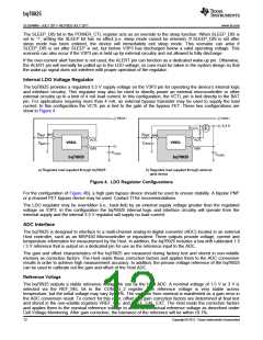
be turned off leaving only the 3.3 V regulator active.
Sleep
In addition to standby, a sleep mode is provided by which the Host can order the bq76925 to shutdown all
internal circuitry including the LDO regulator. In this mode the device will consume a minimal amount of current
(< 1.5 μA) due only to leakage and powering of the wake-up detection circuitry.
Sleep mode is entered by writing a ‘1’ to the SLEEP bit in the POWER_CTL register. In sleep mode, all functions
including the LDO are disabled. Wake-up is achieved by pulling up the ALERT pin; however the wake-up circuitry
is not armed until the voltage at V3P3 drops to ~0 V. To facilitate the discharge of V3P3, an internal 3 kΩ
pull-down is connected from V3P3 to VSS during the time that sleep mode is active. Once V3P3 is discharged,
the bq76925 may be awakened by pulling the ALERT pin above VWAKE (2 V max).
Copyright © 2011, Texas Instruments Incorporated
11

 TI [ TEXAS INSTRUMENTS ]