bq76925
SLUSAM9A –JULY 2011–REVISED JULY 2011
PACK+
www.ti.com
DBAT
BAT
RBAT
VCTL
VREG
ZBAT
CBAT
V3P3
CV3P3
VC6
+
-
bq76925
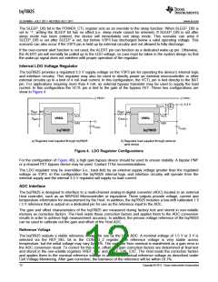
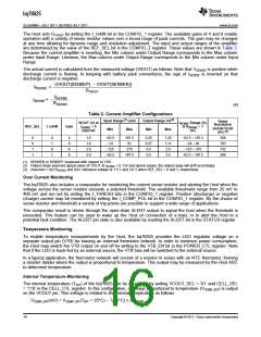
Figure 6. Sources of Voltage Drop Affecting the BAT Pin
The top cell amplifier (VC6 – VC5) is designed to measure an input voltage down to 1.4 V with a difference
between the BAT and VC6 pin up to 1.2 V (i.e. BAT can be 1.2 V lower than VC6). However, in applications with
fewer than 6 cells, the upper cell inputs are typically shorted to the top cell input. For example, in a 5-cell
application VC6 and VC5 would be shorted together and the (VC5 – VC4) amplifier would measure the top cell
voltage. The case is similar for 4- and 3-cell applications.
For these cases when using the (VC5 – VC4), (VC4 –VC3) or (VC3 – VC2) amplifier to measure the top cell, the
difference between BAT and the top cell amplifier must be less than 240 mV in order to measure cell voltages
down to 1.4 V. Note that at higher cell input voltages the top amplifier tolerates a greater difference. For example,
in a 5-cell configuration (VC6 and VC5 tied together) the (VC5 – VC4) amplifier is able to measure down to a 1.7
V input with a 600 mV difference between VC5 and BAT.
Accordingly, in systems with fewer than 6 cells it is important in system design to minimize RBAT and to use a
Schottky type diode for DBAT with a low forward voltage. If it is not possible to reduce the drop at BAT to an
acceptable level, then for 4 and 5 cell configurations the (VC6 – VC5) amplifier may be used as the top cell
amplifier as show in Table 1, which allows up to a 1.2 V difference between BAT and top cell.
Table 1. Alternate Connections for 4 and 5 Cells
Configuration
5-cell
Cell 5
Cell 4
Cell 3
Cell 2
Cell 1
Unused Cell Inputs
Short VC5 to VC4
VC6 – VC5
VC4 – VC3
VC6 – VC5
VC3 – VC2
VC3 – VC2
VC2 – VC1
VC2 – VC1
VC1 – VC0
VC1 – VC0
4-cell
Short VC5 to VC4 to VC3
Current Monitoring
Current is measured by converting current to voltage via a sense resistor connected between SENSEN and
SENSEP. A positive voltage at SENSEP with respect to SENSEN indicates a discharge current is flowing, and a
negative voltage indicates a charge current. The small voltage developed across the sense resistor is amplified
by gain GVIOUT and output on the VIOUT pin for conversion by the Host ADC. The voltage on VIOUT is always
positive and for zero current is set to 3/4 of the output range. The current sense amplifier is inverting; discharge
current causes VIOUT to decrease and charge current causes VIOUT to increase. Therefore, the measurement
range for discharge currents is 3 times the measurement range for charge currents.
The current sense amplifier is preceded by a multiplexer that allows measurement of either the SENSEN or
SENSEP input with respect to VSS. The Host selects the pin for measurement by writing the I_AMP_CAL bit in
the CONFIG_1 register. The Host then calculates the voltage across the sense resistor by subtracting the
measured voltage at SENSEN from the measured voltage at SENSEP. If the SENSEN and VSS connections are
such that charge and discharge currents do not flow through the connection between them, i.e. there is no
voltage drop between SENSEN and VSS due to the current being measured, then the measurement of the
SENSEN voltage can be regarded as a calibration step and stored by the Host for use as a pseudo-constant in
the VSENSE calculation. The SENSEN voltage measurement would then only need updating when changing
environmental conditions warrant.
Copyright © 2011, Texas Instruments Incorporated
15

 TI [ TEXAS INSTRUMENTS ]