bq76925
SLUSAM9A –JULY 2011–REVISED JULY 2011
www.ti.com
The actual cell voltage (VCn) is calculated from the measured voltage (VCOUT) as shown in the following
equations:
ADC Count
VCOUT =
× VREFNOMINAL
Full Scale Count
VCOUT ´ GCVREF + OCVCOUT
VCn =
× (1 + GCVCOUT )
GVCOUT
(1)
spacer
spacer
GCVCOUT
é
ù
=
=
VCn_GC_4 << 4 + VCn_GAIN_CORR ´ 0.001,
)
(
ë
û
é
ë
ù
OCVCOUT
VCn_OC_4 << 4 + VCn_OFFSET_CORR ´ 0.001,
)
û
(
é
ù
GCVREF = (1 + VREF_GC_4 << 4 + VREF_GAIN_CORR ´ 0.001)
( )
ë
û
é
ë
ù
(VREF_OC_5 << 5)+ (VREF_OC_4 << 4)+ VREF_OFFSET_CORR
´ 0.001
û
+
VREFNOMINAL
(2)
Cell Amplifier Headroom Under Extreme Cell Imbalance
For cell voltages across (VC1 – VC0) that are less than ~2.64 V, extreme cell voltage imbalances between
(VC1 – VC0) and (VC2 – VC1) can lead to a loss of gain in the (VC2 – VC1) amplifier. The cell imbalance at
which the loss of gain occurs is determined by the following equation:
(VC2 - VC1) ´ 0.6 > (VC1 - VSS)
(3)
Assuming VC0 = VSS, it can be seen that when (VC1 – VC0) > 2.64 volts, the voltage across (VC2 – VC1) can
range up to the limit of 4.4 V without any loss of gain. At the minimum value of (VC1 – VC0) = 1.4 V, an
imbalance of more than 900 mV is tolerated before any loss of gain in the (VC2 – VC1) amplifier. For higher
values of (VC1 – VC0), increasingly large imbalances are tolerated. For example, when (VC1 – VC0) = 2.0 V, an
imbalance up to 1.33 V (i.e. (VC2 – VC1) = 3.33 V) results in no degradation of amplifier performance.
Normally, cell imbalances greater than 900 mV will signal a faulty condition of the battery pack and its use should
be discontinued. The loss of gain on the second cell input does not affect the ability of the system to detect this
condition. The gain fall-off is gradual so that the measured imbalance will never be less than the critical
imbalance set by Equation 3.
Therefore if the measured (VC2 – VC1) is greater than (VC1 – VSS) / 0.6, a severe imbalance is detected and
the pack should enter a fault state which prevents further use. In this severe cell imbalance condition
comparisons of the measured (VC2 – VC1) to any over-voltage limits will be optimistic due to the reduced gain in
the amplifier, further emphasizing the need to enter a fault state.
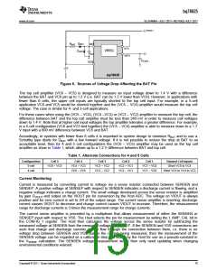
Cell Amplifier Headroom Under BAT Voltage Drop
Voltage differences between BAT and the top cell potential come from two sources as shown in Figure 6: V3P3
regulator current that flows through the RBAT filter resistor, and the voltage drop in the series diode DBAT of the
hold-up circuit. These effects cause BAT to be less than the top cell voltage measured by the cell amplifier.
14
Copyright © 2011, Texas Instruments Incorporated

 TI [ TEXAS INSTRUMENTS ]