AM3359, AM3358, AM3357
AM3356, AM3354, AM3352
SPRS717F –OCTOBER 2011–REVISED APRIL 2013
www.ti.com
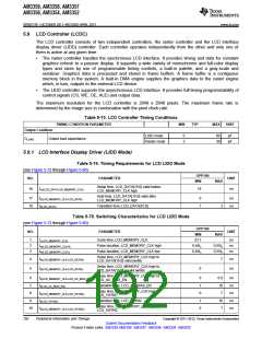
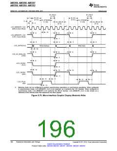
5.9 LCD Controller (LCDC)
The LCD controller consists of two independent controllers, the raster controller and the LCD interface
display driver (LIDD) controller. Each controller operates independently from the other and only one of
them is active at any given time.
•
The raster controller handles the synchronous LCD interface. It provides timing and data for constant
graphics refresh to a passive display. It supports a wide variety of monochrome and full-color display
types and sizes by use of programmable timing controls, a built-in palette, and a gray-scale and
serializer. Graphics data is processed and stored in frame buffers. A frame buffer is a contiguous
memory block in the system. A built-in DMA engine supplies the graphics data to the raster engine
which, in turn, outputs to the external LCD device.
•
The LIDD controller supports the asynchronous LCD interface. It provides full-timing programmability of
control signals (CS, WE, OE, ALE) and output data.
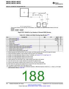
The maximum resolution for the LCD controller is 2048 x 2048 pixels. The maximum frame rate is
determined by the image size in combination with the pixel clock rate.
Table 5-73. LCD Controller Timing Conditions
TIMING CONDITION PARAMETER
MIN
TYP
MAX
UNIT
Output Condition
LIDD mode
5
3
60
30
pF
pF
CLOAD Output load capacitance
Raster mode
5.9.1 LCD Interface Display Driver (LIDD Mode)
Table 5-74. Timing Requirements for LCD LIDD Mode
(see Figure 5-72 through Figure 5-80)
OPP100
NO.
PARAMETER
UNIT
MIN
MAX
Setup time, LCD_DATA[15:0] valid before
LCD_MEMORY_CLK high
16
tsu(LCD_DATA-LCD_MEMORY_CLK)
18
ns
Hold time, LCD_DATA[15:0] valid after
LCD_MEMORY_CLK high
17
18
th(LCD_MEMORY_CLK-LCD_DATA)
tt(LCD_DATA)
0
1
ns
ns
Transition time, LCD_DATA[15:0]
3
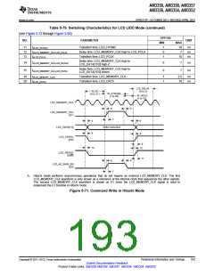
Table 5-75. Switching Characteristics for LCD LIDD Mode
(see Figure 5-72 through Figure 5-80)
OPP100
MIN
NO.
PARAMETER
UNIT
MAX
1
2
3
tc(LCD_MEMORY_CLK)
tw(LCD_MEMORY_CLKH)
tw(LCD_MEMORY_CLKL)
Cycle time, LCD_MEMORY_CLK
23.7
ns
ns
ns
Pulse duration, LCD_MEMORY_CLK high
Pulse duration, LCD_MEMORY_CLK low
0.45tc
0.45tc
0.55tc
0.55tc
Delay time, LCD_MEMORY_CLK high to
LCD_DATA[15:0] valid (write)
4
5
td(LCD_MEMORY_CLK-LCD_DATAV)
td(LCD_MEMORY_CLK-LCD_DATAI)
td(LCD_MEMORY_CLK-LCD_AC_BIAS_EN)
tt(LCD_AC_BIAS_EN)
td(LCD_MEMORY_CLK-LCD_VSYNC)
tt(LCD_VSYNC)
7
ns
ns
Delay time, LCD_MEMORY_CLK high to
LCD_DATA[15:0] invalid (write)
0
Delay time, LCD_MEMORY_CLK high to
LCD_AC_BIAS_EN
6
7
0
1
0
1
0
6.8
10
7
ns
ns
ns
ns
ns
Transition time, LCD_AC_BIAS_EN
Delay time, LCD_MEMORY_CLK high to
LCD_VSYNC
8
9
Transition time, LCD_VSYNC
10
7
Delay time, LCD_MEMORY_CLK high to
LCD_HSYNC
10
td(LCD_MEMORY_CLK-LCD_HYSNC)
192
Peripheral Information and Timings
Copyright © 2011–2013, Texas Instruments Incorporated
Submit Documentation Feedback
Product Folder Links: AM3359 AM3358 AM3357 AM3356 AM3354 AM3352

 TI [ TEXAS INSTRUMENTS ]