AM3359, AM3358, AM3357
AM3356, AM3354, AM3352
www.ti.com
SPRS717F –OCTOBER 2011–REVISED APRIL 2013
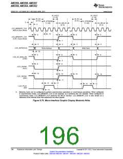
Table 5-75. Switching Characteristics for LCD LIDD Mode (continued)
(see Figure 5-72 through Figure 5-80)
OPP100
UNIT
NO.
PARAMETER
MIN
1
MAX
10
11
12
13
tt(LCD_HSYNC)
Transition time, LCD_HYSNC
ns
ns
ns
td(LCD_MEMORY_CLK-LCD_PCLK)
tt(LCD_PCLK)
Delay time, LCD_MEMORY_CLK high to LCD_PCLK
Transition time, LCD_PCLK
0
7
1
10
Delay time, LCD_MEMORY_CLK high to
LCD_DATA[15:0] high-Z
14
15
td(LCD_MEMORY_CLK-LCD_DATAZ)
td(LCD_MEMORY_CLK-LCD_DATA)
0
0
7
7
ns
ns
Delay time, LCD_MEMORY_CLK high to
LCD_DATA[15:0] driven
19
20
tt(LCD_MEMORY_CLK)
tt(LCD_DATA)
Transition time, LCD_MEMORY_CLK
Transition time, LCD_DATA
1
1
2.5
10
ns
ns
CS_DELAY
(0 to 3)
W_SU
(0 to 31)
W_STROBE
(1 to 63)
W_HOLD
(1 to 15)
LCD_MEMORY_CLK
6
6
LCD_MEMORY_CLK
(E1)
7
4
8
5
8
LCD_DATA[7:0]
Write Instruction
LCD_VSYNC
(RS)
9
10
10
LCD_HSYNC
(R/W)
11
6
6
LCD_AC_BIAS_EN
(E0)
7
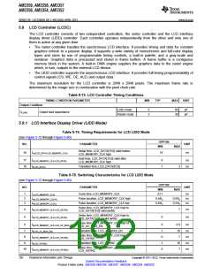
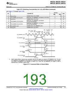
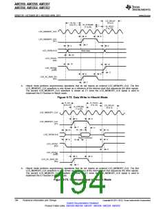
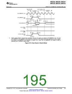
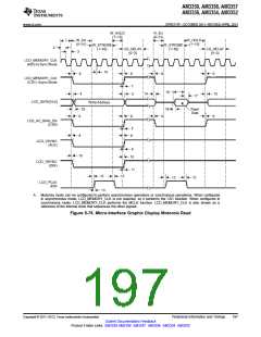
A. Hitachi mode performs asynchronous operations that do not require an external LCD_MEMORY_CLK. The first
LCD_MEMORY_CLK waveform is only shown as a reference of the internal clock that sequences the other signals.
The second LCD_MEMORY_CLK waveform is shown as E1 since the LCD_MEMORY_CLK signal is used to
implement the E1 function in Hitachi mode.
Figure 5-71. Command Write in Hitachi Mode
Copyright © 2011–2013, Texas Instruments Incorporated
Peripheral Information and Timings
193
Submit Documentation Feedback
Product Folder Links: AM3359 AM3358 AM3357 AM3356 AM3354 AM3352

 TI [ TEXAS INSTRUMENTS ]