AM3359, AM3358, AM3357
AM3356, AM3354, AM3352
www.ti.com
SPRS717F –OCTOBER 2011–REVISED APRIL 2013
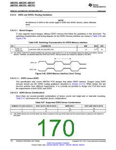
5.6.2.3.3 DDR3 Interface
5.6.2.3.3.1 DDR3 Interface Schematic
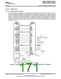
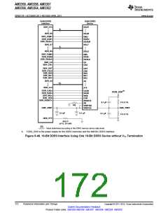
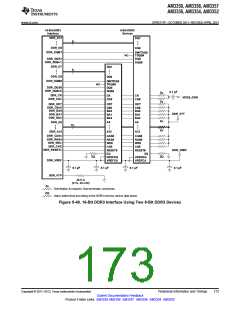
The DDR3 interface schematic varies, depending upon the width of the DDR3 devices used. Figure 5-47
shows the schematic connections for 16-bit interface on AM335x device using one x16 DDR3 device and
Figure 5-49 shows the schematic connections for 16-bit interface on AM335x device using two x8 DDR3
devices. The AM335x DDR3 memory interface only supports 16-bit wide mode of operation. The AM335x
device can only source one load connected to the DQS[x] and DQ[x] net class signals and two loads
connected to the CK and ADDR_CTRL net class signals. For more information related to net classes, see
Section 5.6.2.3.3.8.
16-Bit DDR3
Interface
16-Bit DDR3
Device
DDR_D15
DQU7
8
DDR_D8
DQU0
DDR_DQM1
DDR_DQS1
DDR_DQSn1
DMU
DQSU
DQSU#
DDR_D7
DQL7
8
DDR_D0
DQL0
DDR_DQM0
DDR_DQS0
DDR_DQSn0
DML
DQSL
DQSL#
0.1 µF
Zo
Zo
DDR_CK
CK
VDDS_DDR
DDR_CKn
CK#
DDR_ODT
DDR_CSn0
DDR_BA0
DDR_BA1
DDR_BA2
ODT
CS#
BA0
BA1
BA2
DDR_VTT
Zo
Zo
DDR_A0
A0
15
DDR_A15
A15
DDR_CASn
DDR_RASn
DDR_WEn
CAS#
RAS#
WE#
DDR_CKE
CKE
DDR_RESETn
DDR_VREF
RESET#
ZQ
ZQ
VREFDQ
VREFCA
DDR_VREF
0.1 µF
0.1 µF
0.1 µF
DDR_VTP
49.9 Ω
( 1%, 20 mW)
Zo
ZQ
Termination is required. See terminator comments.
Value determined according to the DDR3 memory device data sheet.
Figure 5-47. 16-Bit DDR3 Interface Using One 16-Bit DDR3 Device with VTT Termination
Copyright © 2011–2013, Texas Instruments Incorporated
Peripheral Information and Timings
171
Submit Documentation Feedback
Product Folder Links: AM3359 AM3358 AM3357 AM3356 AM3354 AM3352

 TI [ TEXAS INSTRUMENTS ]