ADS131M04-Q1
ZHCSOL7A –MARCH 2022 –REVISED AUGUST 2022
www.ti.com.cn
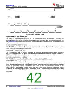
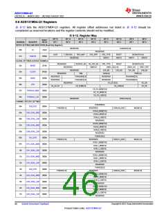
CS
SCLK
DIN
RESET
CRC
RESET command
latched here
DOUT
Hi-Z
Response
Don‘t Care
Don‘t Care
Don‘t Care
Don‘t Care
Don‘t Care
Hi-Z
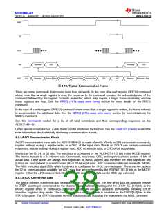
图8-22. RESET Command Frame
8.5.1.10.3 STANDBY (0000 0000 0010 0010)
The STANDBY command places the device in a low-power standby mode. The command is latched by the
device at the end of the frame. The device enters standby mode immediately after the command is latched. See
the Standby Mode section for more information. This command has no effect if the device is already in standby
mode.
8.5.1.10.4 WAKEUP (0000 0000 0011 0011)
The WAKEUP command returns the device to conversion mode from standby mode. This command has no
effect if the device is already in conversion mode.
8.5.1.10.5 LOCK (0000 0101 0101 0101)
The LOCK command locks the interface, preventing the device from accidentally latching unwanted commands
that can change the state of the device. When the interface is locked, the device only responds to the NULL,
RREG, and UNLOCK commands. The device continues to output conversion data even when locked.
8.5.1.10.6 UNLOCK (0000 0110 0101 0101)
The UNLOCK command unlocks the interface if previously locked by the LOCK command.
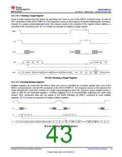
8.5.1.10.7 RREG (101a aaaa annn nnnn)
The RREG is used to read the device registers. The binary format of the command word is 101a aaaa annn
nnnn, where a aaaa a is the binary address of the register to begin reading and nnn nnnn is the unsigned binary
number of consecutive registers to read minus one. There are two cases for reading registers on the
ADS131M04-Q1. When reading a single register (nnn nnnn = 000 0000b), the device outputs the register
contents in the command response word of the following frame. If multiple registers are read using a single
command (nnn nnnn > 000 0000b), the device outputs the requested register data sequentially in order of
addresses.
Copyright © 2022 Texas Instruments Incorporated
42
Submit Document Feedback
Product Folder Links: ADS131M04-Q1

 TI [ TEXAS INSTRUMENTS ]