ADS1291
ADS1292
ADS1292R
www.ti.com
SBAS502A –DECEMBER 2011–REVISED MARCH 2012
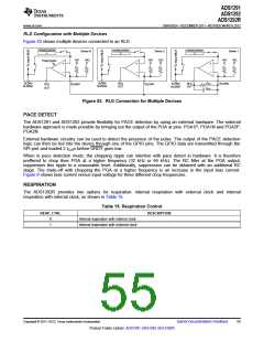
RLD Configuration with Multiple Devices
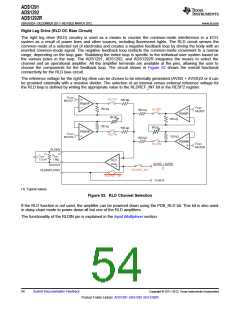
Figure 53 shows multiple devices connected to an RLD.
(AVDD+AVSS)
2
(AVDD+AVSS)
2
(AVDD+AVSS)
2
Device N
VA2
Device 2
VA2
Device 1
VA2
VA1
VA1
VA1
Power-Down
RLDIN/
RLDREF
RLDIN/
RLDREF
REXT
CEXT
RLD
OUT
RLD
OUT
RLDIN/
RLDREF
RLDINV
RLDINV
RLDINV
RLD
OUT
Figure 53. RLD Connection for Multiple Devices
PACE DETECT
The ADS1291 and ADS1292 provide flexibility for PACE detection by using an external hardware. The external
hardware approach is made possible by bringing out the output of the PGA at pins: PGA1P, PGA1N and PGA2P,
PGA2N.
External hardware circuitry can be used to detect the presence of the pulse. The output of the PACE detection
logic can then be fed into the device through one of the GPIO pins. The GPIO data are transmitted through the
SPI port and loaded 2 tCLKs before DRDY goes low.
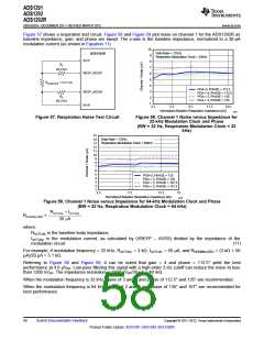
When in pace detection mode, the chopping ripple can interfere with pace detect in hardware. It is therefore
preffered to chop thee PGA at a higher frequency (32 kHz or 64 kHz). The RC filter at the PGA output,
suppresses this ripple to a reasonable level. Additionally, suppression can be obtained with an additional RC
stage. The trade-off with chopping the PGA at a higher frequency is an increase in the input bias current.
Figure 6 shows bias current versus input voltage for three different chop frequencies.
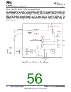
RESPIRATION
The ADS1292R provides two options for respiration: internal respiration with external clock and internal
respiration with internal clock, as shown in Table 15.
Table 15. Respiration Control
RESP_CTRL
DESCRIPTION
0
1
Internal respiration with internal clock
Internal respiration with external clock
Copyright © 2011–2012, Texas Instruments Incorporated
Submit Documentation Feedback
55
Product Folder Link(s): ADS1291 ADS1292 ADS1292R

 TI [ TEXAS INSTRUMENTS ]