ADS1291
ADS1292
ADS1292R
www.ti.com
SBAS502A –DECEMBER 2011–REVISED MARCH 2012
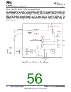
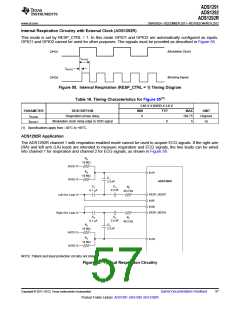
Internal Respiration Circuitry with External Clock (ADS1292R)
This mode is set by RESP_CTRL = 1. In this mode GPIO1 and GPIO2 are automatically configured as inputs.
GPIO1 and GPIO2 cannot be used for other purposes. The signals must be provided as described in Figure 55.
(Modulation Clock)
GPIO1
tPHASE
tBLKDLY
(Blocking Signal)
GPIO2
Figure 55. Internal Respiration (RESP_CTRL = 1) Timing Diagram
Table 16. Timing Characteristics for Figure 55(1)
1.65 V ≤ DVDD ≤ 3.6 V
PARAMETER
tPHASE
DESCRIPTION
MIN
TYP
MAX
168.75
5
UNIT
Degrees
ns
Respiration phase delay
0
tBLKDLY
Modulation clock rising edge to XOR signal
0
(1) Specifications apply from –40°C to +85°C.
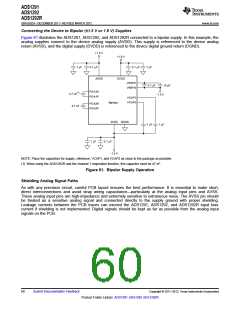
ADS1292R Application
The ADS1292R channel 1 with respiration enabled mode cannot be used to acquire ECG signals. If the right arm
(RA) and left arm (LA) leads are intended to measure respiration and ECG signals, the two leads can be wired
into channel 1 for respiration and channel 2 for ECG signals, as shown in Figure 56.
R6
10 MW
AVDD
R5
IN1P
10 MW
C1
AVSS
ADS1292R
2.2 nF
C2
C3
R2
2.2 nF
0.1 mF
40.2 kW
RESP_MODP
IN2P
Left Arm Lead
IN2N
RESP_MODN
Right Arm Lead
C6
C4
R1
2.2 nF
0.1 mF
40.2 kW
R4
C5
2.2 nF
10 MW
AVDD
AVSS
R3
IN1N
10 MW
NOTE: Patient and input protection circuitry not shown.
Figure 56. Typical Respiration Circuitry
Copyright © 2011–2012, Texas Instruments Incorporated
Submit Documentation Feedback
57
Product Folder Link(s): ADS1291 ADS1292 ADS1292R

 TI [ TEXAS INSTRUMENTS ]