ADS1291
ADS1292
ADS1292R
SBAS502A –DECEMBER 2011–REVISED MARCH 2012
www.ti.com
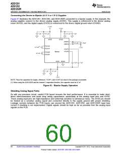
Internal Respiration Circuitry with Internal Clock (ADS1292R)
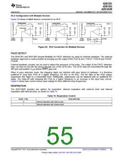
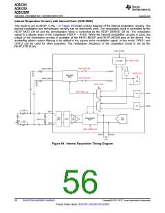
This mode is set by RESP_CTRL = 0. Figure 54 shows a block diagram of the internal respiration circuitry. The
internal modulation and demodulator circuitry can be selectively used. The modulation block is controlled by the
RESP_MOD_EN bit and the demodulation block is controlled by the RESP_DEMOD_EN bit. The modulation
signal is a square wave of the magnitude VREFP – AVSS. When the internal modulation circuitry is used, the
output of the modulation circuitry is available at the RESP_MODP and RESP_MODM pins of the device. This
availability allows custom filtering to be added to the square wave modulation signal. In this mode, GPIO1 and
GPIO2 can be used for other purposes. The modulation frequency of the respiration circuit is set by the
RESP_FREQ bits.
CLK (512 kHz)
RESP_FREQ
CLK GEN
RESP_MOD_EN
RESP_MOD_EN
RESP_MODP
RESP_MODN
VREFP
RESP_CTRL
Modulation
Block
AVSS
I/O
I/O
I/O
RESP_CTRL
RESP_MOD_CLK
GPIO1
GPIO2
IN1P
Ch1
ADC
EMI
Filter
Ch1
PGA
Demodulation
VBIAS
MUX
Block
IN1N
RESP_DEMOD_EN
PGA1P
PGA1N
47 nF
Figure 54. Internal Respiration Timing Diagram
56
Submit Documentation Feedback
Copyright © 2011–2012, Texas Instruments Incorporated
Product Folder Link(s): ADS1291 ADS1292 ADS1292R

 TI [ TEXAS INSTRUMENTS ]