ADS1291
ADS1292
ADS1292R
SBAS502A –DECEMBER 2011–REVISED MARCH 2012
www.ti.com
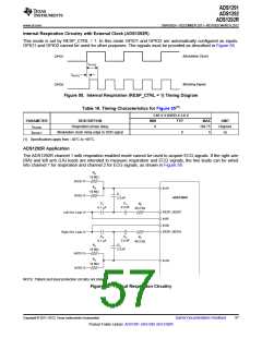
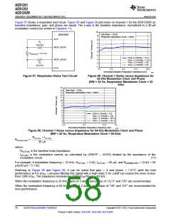
Figure 57 shows a respiration test circuit. Figure 58 and Figure 59 plot noise on channel 1 for the ADS1292R as
baseline impedance, gain, and phase are swept. The x-axis is the baseline impedance, normalized to a 30-µA
modulation current (as shown in Equation 11).
10
Data Rate = 125Hz
Respiration Modulation Clock = 32kHz
ADS1292R
9
IN1P
8
R2
7
40.2 kW
RESP_MODP
6
5
RBASELINE = 2.21 kW
4
PGA=3, PHASE = 112.5
3
2
1
RESP_MODN
IN1N
PGA = 4, PHASE = 112.5
PGA = 3, PHASE = 135
PGA = 4, PHASE = 135
R2
40.2 kW
2.2
5.2
8.2
11.2
14.2
Normalized Baseline Respiration Impedance (kΩ)
G058
Figure 57. Respiration Noise Test Circuit
Figure 58. Channel 1 Noise versus Impedance for
32-kHz Modulation Clock and Phase
(BW = 32 Hz, Respiration Modulation Clock = 32
kHz)
15
Data Rate = 125Hz
Respiration Modulation Clock = 64kHz
14
13
12
11
10
9
8
7
6
5
4
3
2
PGA=2, PHASE = 135
PGA = 3, PHASE = 135
PGA = 2, PHASE = 157.5
PGA = 3, PHASE = 157.5
1
2.2
7.2
12.2
15
Normalized Baseline Respiration Impedance (kΩ)
G059
Figure 59. Channel 1 Noise versus Impedance for 64-kHz Modulation Clock and Phase
(BW = 32 Hz, Respiration Modulation Clock = 64 kHz)
RACTUAL ´ IACTUAL
RNORMALIZED
=
30 mA
where:
RACTUAL is the baseline body impedance,
IACTUAL is the modulation current, as calculated by (VREFP – AVSS) divided by the impedance of the
modulation circuit.
(11)
For example, if modulation frequency = 32 kHz, RACTUAL = 3 kΩ, IACTUAL = 50 µA, and RNORMALIZED = (3 kΩ × 50
µA)/29 µA = 5.1 kΩ.
Referring to Figure 58 and Figure 59, it can be noted that gain = 4 and phase = 112.5° yield the best
performance at 4.6 µVPP. Low-pass filtering this signal with a high-order 2-Hz cutoff can reduce the noise to less
than 1200 nVPP. The impedance resolution is 1200 nVPP/30 µA = 40 mΩ.
When the modulation frequency is 32 kHz, gains of 3 and 4 and phase of 112.5° and 135° are recommended.
When the modulation frequency is 64 kHz, gains of 2 and 3 and phase of 135° and 157° are recommended for
best performance.
58
Submit Documentation Feedback
Copyright © 2011–2012, Texas Instruments Incorporated
Product Folder Link(s): ADS1291 ADS1292 ADS1292R

 TI [ TEXAS INSTRUMENTS ]