ADS1291
ADS1292
ADS1292R
www.ti.com
SBAS502A –DECEMBER 2011–REVISED MARCH 2012
LEAD-OFF DETECTION
Patient electrode impedances are known to decay over time. It is necessary to continuously monitor these
electrode connections to verify a suitable connection is present. The ADS1291, ADS1292, and ADS1292R lead-
off detection functional block provides significant flexibility to the user to choose from various lead-off detection
strategies. Though called lead-off detection, this is in fact an electrode-off detection.
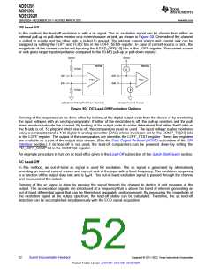
The basic principle is to inject an excitation signal and measure the response to find out if the electrode is off. As
shown in the lead-off detection functional block diagram in Figure 49, this circuit provides two different methods
of determining the state of the patient electrode. The methods differ in the frequency content of the excitation
signal. Lead-off can be selectively done on a per channel basis using the LOFF_SENS register. Also, the internal
excitation circuitry can be disabled and just the sensing circuitry can be enabled.
Skin,
Patient
Patient Electrode Contact Protection
Model
Resistor
47 nF
51 k
IN1P_OFF/
IN2P_OFF
30 k
30 k
VINP
VINN
EMI
Filter
PGA
To ADC
51 k
LOFF1P/
LOFF2P
LOFF1N/
LOFF2N
47 nF
IN1N_OFF/
IN2N_OFF
47 nF
51 k
4-Bit
DAC
AVDD AVSS
COMP_TH[2:0]
30 k
RLD OUT
NOTE: The RP value must be selected in order to be below the maximum allowable current flow into a patient (in accordance with the
relevant specification the latest revision of IEC 60601).
Figure 49. Lead-Off Detection
Copyright © 2011–2012, Texas Instruments Incorporated
Submit Documentation Feedback
51
Product Folder Link(s): ADS1291 ADS1292 ADS1292R

 TI [ TEXAS INSTRUMENTS ]