ADS1291
ADS1292
ADS1292R
www.ti.com
SBAS502A –DECEMBER 2011–REVISED MARCH 2012
RLD Lead-Off
The ADS1291, ADS1292, and ADS1292R provide two modes for determining whether the RLD is correctly
connected:
•
•
RLD lead-off detection during normal operation
RLD lead-off detection during power-up
The following sections provide details of the two modes of operation.
RLD Lead-Off Detection During Normal Operation
During normal operation, the ADS1291, ADS1292, and ADS1292R RLD lead-off at power-up function cannot be
used because it is necessary to power off the RLD amplifier.
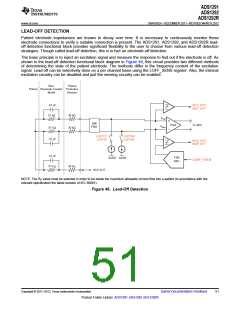
RLD Lead-Off Detection At Power-Up
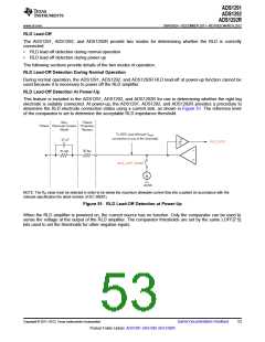
This feature is included in the ADS1291, ADS1292, and ADS1292R for use in determining whether the right leg
electrode is suitably connected. At power-up, the ADS1291, ADS1292, and ADS1292R provides a procedure to
determine the RLD electrode connection status using a current sink, as shown in Figure 51. The reference level
of the comparator is set to determine the acceptable RLD impedance threshold.
Skin,
Patient
Patient Electrode Contact Protection
Model
47 nF
Resistor
To ADC input (through VREF
connection to any of the channels).
RLD_STAT
30 k
51 k
RLD_LOFF_SENS
AVSS
NOTE: The RP value must be selected in order to be below the maximum allowable current flow into a patient (in accordance with the
relevant specification the latest revision of IEC 60601).
Figure 51. RLD Lead-Off Detection at Power-Up
When the RLD amplifier is powered on, the current source has no function. Only the comparator can be used to
sense the voltage at the output of the RLD amplifier. The comparator thresholds are set by the same LOFF[7:5]
bits used to set the thresholds for other negative inputs.
Copyright © 2011–2012, Texas Instruments Incorporated
Submit Documentation Feedback
53
Product Folder Link(s): ADS1291 ADS1292 ADS1292R

 TI [ TEXAS INSTRUMENTS ]