ADS1291
ADS1292
ADS1292R
www.ti.com
SBAS502A –DECEMBER 2011–REVISED MARCH 2012
ECG-SPECIFIC FUNCTIONS
INPUT MULTIPLEXER (REROUTING THE RIGHT LEG DRIVE SIGNAL)
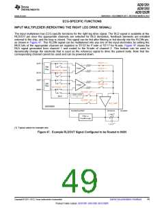
The input multiplexer has ECG-specific functions for the right leg drive signal. The RLD signal is available at the
RLDOUT pin once the appropriate channels are selected for RLD derivation, feedback elements are installed
external to the chip, and the loop is closed. This signal can be fed after filtering or fed directly into the RLDIN pin,
as shown in Figure 47. This RLDIN signal can be multiplexed into any one of the input electrodes by setting the
MUX bits of the appropriate channel set registers to '0110' for P-side or '0111' for N-side. Figure 47 shows the
RLD signal generated from channel 1 and routed to the N-side of channel 2. This feature can be used to
dynamically change the electrode that is used as the reference signal to drive the patient body. Note that the
corresponding channel cannot be used and can be powered down.
RLD1P = 1
IN1P
EMI
Filter
PGA1
PGA2
RLD1N = 1
MUX1[3:0] = 0000
IN1N
IN2P
RLD2P = 0
RLD2N = 0
EMI
Filter
MUX1[3:0] = 0111
IN2N
RLDREF_INT = 1
(AVDD + AVSS)
MUX
2
RLDREF_INT = 0
RLD_AMP
ADS1292R
RLDIN/RLDREF
RLDOUT
RLDINV
(1)
1 M
Filter or
Feedthrough
1.5 nF(1)
(1) Typical values for example only.
Figure 47. Example RLDOUT Signal Configured to be Routed to IN2N
Copyright © 2011–2012, Texas Instruments Incorporated
Submit Documentation Feedback
49
Product Folder Link(s): ADS1291 ADS1292 ADS1292R

 TI [ TEXAS INSTRUMENTS ]