ADS1299
SBAS499A –JULY 2012–REVISED AUGUST 2012
www.ti.com
SPI INTERFACE
The SPI-compatible serial interface consists of four signals: CS, SCLK, DIN, and DOUT. The interface reads
conversion data, reads and writes registers, and controls ADS1299 operation. The DRDY output is used as a
status signal to indicate when data are ready. DRDY goes low when new data are available.
Chip Select (CS)
Chip select (CS) selects the ADS1299 for SPI communication. CS must remain low for the entire serial
communication duration. After the serial communication is finished, always wait four or more tCLK cycles before
taking CS high. When CS is taken high, the serial interface is reset, SCLK and DIN are ignored, and DOUT
enters a high-impedance state. DRDY asserts when data conversion is complete, regardless of whether CS is
high or low.
Serial Clock (SCLK)
SCLK is the serial peripheral interface (SPI) serial clock. SCLK shifts in commands and shifts out data from the
device. SCLK features a Schmitt-triggered input and clocks data on the DIN and DOUT pins into and out of the
ADS1299. Even though the input has hysteresis, it is recommended to keep SCLK as clean as possible to
prevent glitches from accidentally forcing a clock event. The absolute maximum SCLK limit is specified in the
Serial Interface Timing table. When shifting in commands with SCLK, make sure that the entire set of SCLKs is
issued to the device. Failure to do so can result in the device serial interface being placed into an unknown state,
thus requiring CS to be taken high to recover.
For a single device, the minimum speed required for SCLK depends on the number of channels, number of bits
of resolution, and output data rate. (For multiple cascaded devices, see the Standard Mode subsection of the
Multiple Device Configuration section.)
For example, if the ADS1299 is used in a 500-SPS mode (8 channels, 24-bit resolution), the minimum SCLK
speed is 110 kHz.
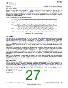
Data retrieval can be accomplished either by placing the device in RDATAC mode or by issuing an RDATA
command for data on demand. The SCLK rate limitation in Equation 6 applies to RDATAC. For the RDATA
command, the limitation applies if data must be read in between two consecutive DRDY signals. Equation 6
assumes that there are no other commands issued in between data captures.
tDR - 4 tCLK
tSCLK
<
N
BITS ´ NCHANNELS + 24
(6)
Data Input (DIN)
The data input pin (DIN) is used along with SCLK to communicate with the ADS1299 (opcode commands and
register data). The device latches data on DIN on the SCLK falling edge.
26
Submit Documentation Feedback
Copyright © 2012, Texas Instruments Incorporated
Product Folder Link(s): ADS1299

 TI [ TEXAS INSTRUMENTS ]