AN1007
Application Notes
Time Delay Relay Circuit
IR Motion Control
An example of a more complex triac switch is an infrared (IR)
motion detector controller circuit. Some applications for this cir-
cuit are alarm systems, automatic lighting, and auto doorbells.
By combining a 555 timer IC with a triac, various time delays of
several seconds can be achieved for delayed activation of solid
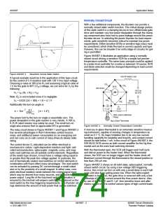
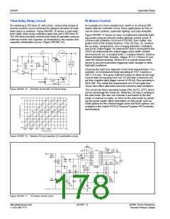
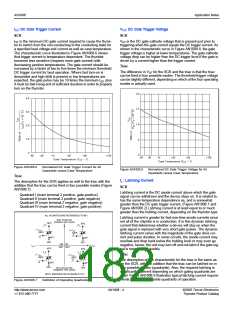
state relays or switches. Figure AN1007.15 shows a solid state
timer delay relay using a sensitive gate triac and a 555 timer IC.
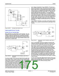
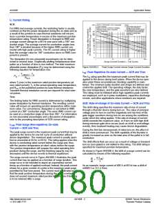
The 555 timer precisely controls time delay of operation using an
external resistor and capacitor, as illustrated by the resistor and
capacitor combination curves. (Figure AN1007.16)
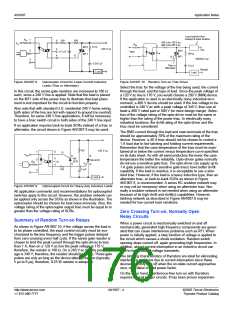
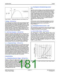
Figure AN1007.17 shows an easy- to-implement automatic light-
ing system using an infrared motion detector control circuit. A
commercially available LSI circuit HT761XB, from Holtek, inte-
grates most of the analog functions. This LSI chip, U2, contains
the op amps, comparators, zero crossing detection, oscillators,
and a triac output trigger. An external RC that is connected to the
OSCD pin determines the output trigger pulse width. (Holtek
Semiconductor Inc. is located at No.3, Creation Road II, Science-
Based Industrial Park, Hsinchu, Taiwan, R.O.C.) Device U1 pro-
vides the infrared sensing. Device R13 is a photo sensor that
serves to prevent inadvertent triggering under daylight or other
high light conditions.
Choosing the right triac depends on the load characteristics. For
example, an incandescent lamp operating at 110 V requires a
200 V, 8 A triac. This gives sufficient margin to allow for the high
current state during lamp burn out. U2 provides a minimum out-
put triac negative gate trigger current of 40 mA, thus operating in
QII & QIII. This meets the requirements of a 25 mA gate triac.
Teccor also offers alternistor triacs for inductive load conditions.
This circuit has three operating modes (ON, AUTO, OFF), which
can be set through the mode pin. While the LSI chip is working in
the auto mode, the user can override it and switch to the test
mode, or manual on mode, or return to the auto mode by switch-
ing the power switch. More information on this circuit, such as
mask options for the infrared trigger pulse and flash options, are
available in the Holtek HT761X General Purpose PIR Controller
specifications.
1 K
LOAD
MT2
10 K
3
8
MT1
G
4
2
5
R
10 M
6
7
120 V
60 Hz
555
1
C
1 µF
0.1 µF
0.01 µF
1N4003
-10 V
_
+
3.5 K
250 V
1N4740
10 µF
Figure AN1007.15 555 timer circuit with 10 second delay
100
10
1.0
0.1
0.01
0.001
10ms
100ms
1ms
10ms
100ms
1.0
10
100
t
TIME DELAY (s)
d
Figure AN1007.16 Resistor (R) and capacitor (C) combination curves
C7
3900pF
R6
1M
C6
22µF
R5
22K
C3
100pF
U2
1
2
C5
0.02µF
16
15
VSS
OP20
OP2N
OP2P
OP10
OP1N
OP1P
RSTB
VEE
AC+
110
TRIAC
OSCD
OSCS
ZC
14
13
R7
1M
3
4
5
6
SW1
ON/OFF
OVERRIDE
C8
0.1µF
12
11
R8 569K
LP1
Lamp
60 to
600
R4
1M
R9
1M
D3
1N4002
CDS
10
9
C12
22µF
C2
0.02µF
7
8
R12
22K
MODE
VDD
Watt
R2
2.4M
SW2
Mode
HT761XB
-16 DIP/SOP
C13
0.02µF
R9
1M
D5
1N4002
D4
1N4002
R14
68W 2W
R3
C9
10µF
56K
C4
100µF
C10
0.33µF
350V
*R10
3
2
U1
PIR
SD622
(Nippon
G
S
Q1
TRIAC
D
1
Q2008L4
D2
1N4002
D1
12V
Ceramic)
R13
CDS
C11
330µF
C1
100µF
AC
Figure AN1007.17 I R motion control circuit
http://www.teccor.com
+1 972-580-7777
AN1007 - 6
©2002 Teccor Electronics
Thyristor Product Catalog

 TECCOR [ TECCOR ELECTRONICS ]