AN1008
Application Notes
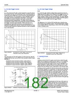
IGT: DC Gate Trigger Current
SCR
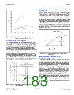
VGT: DC Gate Trigger Voltage
SCR
I
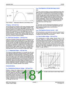
GT is the minimum DC gate current required to cause the thyris-
VGT is the DC gate-cathode voltage that is present just prior to
tor to switch from the non-conducting to the conducting state for
a specified load voltage and current as well as case temperature.
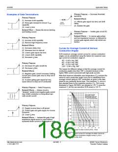
The characteristic curve illustrated in Figure AN1008.6 shows
that trigger current is temperature dependent. The thyristor
becomes less sensitive (requires more gate current) with
decreasing junction temperatures. The gate current should be
increased by a factor of two to five times the minimum threshold
DC trigger current for best operation. Where fast turn-on is
demanded and high di/dt is present or low temperatures are
expected, the gate pulse may be 10 times the minimum IGT, plus
it must be fast-rising and of sufficient duration in order to properly
turn on the thyristor.
triggering when the gate current equals the DC trigger current. As
shown in the characteristic curve in Figure AN1008.8, the gate
trigger voltage is higher at lower temperatures. The gate-cathode
voltage drop can be higher than the DC trigger level if the gate is
driven by a current higher than the trigger current.
Triac
The difference in VGT for the SCR and the triac is that the triac
can be fired in four possible modes. The threshold trigger voltage
can be slightly different, depending on which of the four operating
modes is actually used.
2.0
1.5
1.0
.5
4.0
3.0
2.0
1.0
0
0
-65
-40
-15
+25
+65
+125
-65
-40
-15
+25
+65
+125
Case Temperature (TC) – ˚C
Case Temperature (T ) – ˚C
C
Figure AN1008.6
Normalized DC Gate Trigger Current for All
Quadrants versus Case Temperature
Figure AN1008.8
Normalized DC Gate Trigger Voltage for All
Quadrants versus Case Temperature
Triac
IL: Latching Current
SCR
Latching current is the DC anode current above which the gate
signal can be withdrawn and the device stays on. It is related to,
has the same temperature dependence as, and is somewhat
greater than the DC gate trigger current. (Figure AN1008.1 and
Figure AN1008.2) Latching current is at least equal to or much
greater than the holding current, depending on the thyristor type.
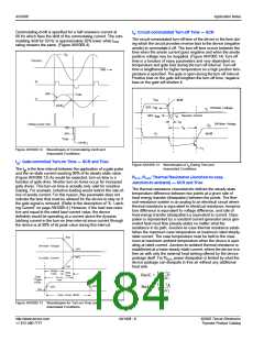
The description for the SCR applies as well to the triac with the
addition that the triac can be fired in four possible modes (Figure
AN1008.7):
Quadrant I (main terminal 2 positive, gate positive)
Quadrant II (main terminal 2 positive, gate negative)
Quadrant III (main terminal 2 negative, gate negative)
Quadrant IV (main terminal 2 negative, gate positive)
ALL POLARITIES ARE REFERENCED TO MT1
Latching current is greater for fast-rise-time anode currents since
not all of the chip/die is in conduction. It is this dynamic latching
current that determines whether a device will stay on when the
gate signal is replaced with very short gate pulses. The dynamic
latching current varies with the magnitude of the gate drive cur-
rent and pulse duration. In some circuits, the anode current may
oscillate and drop back below the holding level or may even go
negative; hence, the unit may turn off and not latch if the gate sig-
nal is removed too quickly.
MT2 POSITIVE
(Positive Half Cycle)
MT2
MT2
+
(-)
IGT
GATE
(+)
IGT
GATE
MT1
MT1
REF
MT2
REF
MT2
QII QI
QIII QIV
IGT
-
+ IGT
(-)
IGT
GATE
Triac
(+)
I
GT
GATE
The description of this characteristic for the triac is the same as
for the SCR, with the addition that the triac can be latched on in
four possible modes (quadrants). Also, the required latching is
significantly different depending on which gating quadrants are
used. Figure AN1008.9 illustrates typical latching current require-
ments for the four possible quadrants of operation.
MT1
REF
MT1
REF
-
MT2 NEGATIVE
(Negative Half Cycle)
NOTE: Alternistors will not operate in Q IV
Figure AN1008.7
Definition of Operating Quadrants
http://www.teccor.com
+1 972-580-7777
AN1008 - 4
©2002 Teccor Electronics
Thyristor Product Catalog

 TECCOR [ TECCOR ELECTRONICS ]