Application Notes
AN1007
tally that general purpose AC circuits will generate minimum
electromagnetic interference (EMI) if energized at zero voltage.
The ideal AC circuit switch, therefore, consists of a contact which
closes at the instant when voltage across it is zero and opens at
the instant when current through it is zero. This has become
known as “zero-voltage switching.”
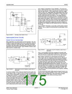
For applications that require synchronized zero-crossing turn-on,
the illustration in Figure AN1007.11 shows a circuit which incor-
porates an optocoupler with a built-in zero-crossing detector
Load could be here
instead of lower location
22
R
in
6
5
1
2
Hot
MT2
MT1
Input
100 Ω
G
120/240 V ac
4
Zero
Crossing
Circuit
3
Triac or
0.1µf
Alternistor
Neutral
Load
R
22
in
1
6
5
V
cc
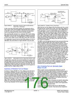
Figure AN1007.12 Zero Crossing Turn-on Opto Triac Driver
Hot
MT2
MT1
100
2
3
120 V ac
Load
4
G
Non-sensitive Gate SCRs
Zero
Crossing
Circuit
0.1 µF
100
R
in
1
6
G
Neutral
K
A
A
K
120/240 V ac
Load
Input
5
4
G
2
3
Zero
Crossing
Circuit
22
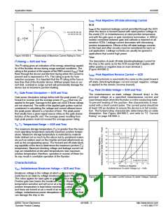
Figure AN1007.11 Optocoupled Circuit with Zero-crossing Turn-on
(Triac or Alternistor)
0.1µF
Also, this circuit includes a dv/dt snubber network connected
across the power triac. This typical circuit illustrates switching the
hot line; however, the load may be connected to either the hot or
neutral line. Also, note that the series gate resistor is low in value
(22 Ω), which is possible on a 120 V line and above, since zero-
crossing turn-on is ensured in any initial half cycle.
Load could be here
instead of lower location
Figure AN1007.13 Zero Crossing Turn-on Non-sensitive SCR Driver
Load
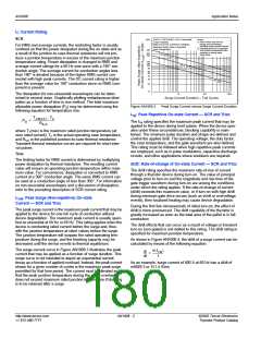
Sensitive Gate SCRs
1 K
Summary of Zero Crossing Turn-on Circuits
100
*
R
in
1
6
G
Zero voltage crossing turn-on opto-drivers are designed to limit
turn-on voltage to less than 20 V. This reduces the amount of RFI
and EMI generated when the thyristor switches on. Because of
this zero turn-on, these devices cannot be used to phase control
loads. Therefore, speed control of a motor and dimming of a
lamp cannot be accomplished with zero turn-on opto-couplers.
Since the voltage is limited to 20 V or less, the series gate resis-
tor that limits the gate drive current has to be much lower with a
zero crossing opto-driver. With typical inhibit voltage of 5 V, an
alternistor triac gate could require a 160 mA at -30 °C (5 V/
0.16 A = 31 Ω gate resistor). If the load has a high inrush current,
then drive the gate of the triac with as much current as reliably
possible but stay under the ITSM rating of the opto-driver. By using
22 Ω for the gate resistor, a current of at least 227 mA is supplied
with only 5 V, but limited to 909 mA if the voltage goes to 20 V. As
shown in Figure AN1007.12, Figure AN1007.13, and Figure
AN1007.14, a 22 Ω gate resistor is a good choice for various
zero crossing controllers.
K
A
A
K
120/240 V ac
Input
5
4
G
2
3
22
1 K
Zero
Crossing
Circuit
*
0.1 µF
Gate Diodes to Have
Same PIV as SCRs
Load could be here
instead of lower location
*
Figure AN1007.14 Zero Crossing Turn-on Opto-sensitive Gate SCR
Driver
©2002 Teccor Electronics
Thyristor Product Catalog
AN1007 - 5
http://www.teccor.com
+1 972-580-7777

 TECCOR [ TECCOR ELECTRONICS ]