Application Notes
AN1008
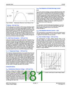
IDRM: Peak Repetitive Off-state (Blocking) Current
SCR
I
di/dt
I
DRM is the maximum leakage current permitted through the SCR
ITM
when the device is forward biased with rated positive voltage on
the anode (DC or instantaneous) at rated junction temperature
and with the gate open or gate resistance termination. A 1000 Ω
resistor connected between gate and cathode is required on all
sensitive SCRs. Leakage current decreases with decreasing
junction temperatures. Effects of the off-state leakage currents
on the load and other circuitry must be considered for each cir-
cuit application. Leakage currents can usually be ignored in
applications that control high power.
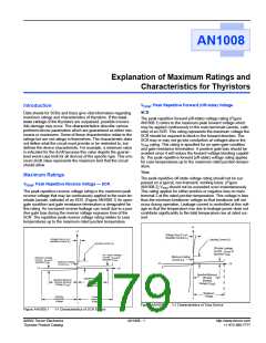
t = 8.3 ms for 60 Hz
10 ms for 50 Hz
(ITM
t
)
di
dt
=
Time
0
t
Relationship of Maximum Current Rating to Time
Figure AN1008.4
Triac
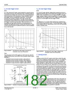
I2t Rating — SCR and Triac
The description of peak off-state (blocking/leakage) current for
the triac is the same as for the SCR except that it applies with
either positive or negative bias on main terminal 2.
(Figure AN1008.2)
The I2t rating gives an indication of the energy-absorbing capabil-
ity of the thyristor device during surge-overload conditions. 2The
rating is the product of the square of the RMS current (IRMS) that
flows through the device and the time during which the current is
present and is expressed in A2s. This rating is given for fuse
selection purposes. It is important that the I2t rating of the fuse is
less than that of the thyristor device. Without proper fuse or cur-
rent limit, overload or surge current will permanently damage the
device due to excessive junction heating.
IRRM: Peak Repetitive Reverse Current — SCR
This characteristic is essentially the same as the peak forward
off-state (blocking/leakage) current except negative voltage
is applied to the anode (reverse biased).
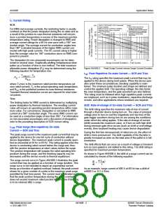
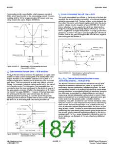
VTM: Peak On-State Voltage — SCR and Triac
PG: Gate Power Dissipation — SCR and Triac
The instantaneous on-state voltage (forward drop) is the
principal voltage at a specified instantaneous current and
case temperature when the thyristor is in the conducting state.
To prevent heating of the junction, this characteristic is mea-
sured with a short current pulse. The current pulse should be
at least 100 µs duration to ensure the device is in full conduc-
tion. The forward-drop characteristic determines the on-state
dissipation. See Figure AN1008.5, and refer to “IT: Current
Rating” on page AN1008-2.
Gate power dissipation ratings define both the peak power (PGM
forward or reverse and the average power (PG(AV)) that may be
)
applied to the gate. Damage to the gate can occur if these ratings
are not observed. The width of the applied gate pulses must be
considered in calculating the voltage and current allowed since
the peak power allowed is a function of time. The peak power
that results from a given signal source relies on the gate charac-
teristics of the specific unit. The average power resulting from
high peak powers must not exceed the average-power rating.
TS, TJ: Temperature Range — SCR and Triac
90
80
The maximum storage temperature (TS) is greater than the maxi-
mum operating temperature (actually maximum junction temper-
ature). Maximum storage temperature is restricted by material
limits defined not so much by the silicon but by peripheral materi-
als such as solders used on the chip/die and lead attachments as
well as the encapsulating epoxy. The forward and off-state block-
ing capability of the device determines the maximum junction (TJ)
temperature. Maximum blocking voltage and leakage current rat-
ings are established at elevated temperatures near maximum
junction temperature; therefore, operation in excess of these lim-
its may result in unreliable operation of the thyristor.
=
T
25 ˚C
C
70
60
50
40
30
20
10
0
40 A TO-218
15 and 25 A TO-220
1.2 1.4 1.6 1.8
Characteristics
0
0.6
0.8
1.0
Positive or Negative
Instantaneous On-state Voltage (v ) – Volts
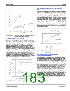
VBO: Instantaneous Breakover Voltage — SCR and Triac
T
Breakover voltage is the voltage at which a device turns on
(switches to on state by voltage breakover). (Figure AN1008.1)
This value applies for open-gate or gate-resistance termination.
Positive gate bias lowers the breakover voltage. Breakover is
temperature sensitive and will occur at a higher voltage if the
Figure AN1008.5
On-state Current versus On-state Voltage (Typical)
junction temperature is kept below maximum T value. If SCRs
J
and triacs are turned on as a result of an excess of breakover
voltage, instantaneous power dissipations may be produced that
can damage the chip or die.
©2002 Teccor Electronics
Thyristor Product Catalog
AN1008 - 3
http://www.teccor.com
+1 972-580-7777

 TECCOR [ TECCOR ELECTRONICS ]