Application Notes
AN1007
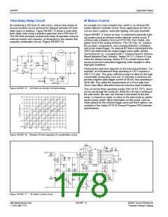
wave voltage as illustrated in Figure AN1007.2. The load resis-
tance is also important, since it can also limit the amount of avail-
able triac gate current. A 100 Ω gate resistor would be a better
choice in most 120 V applications with loads greater than 200 W
and optocouplers from Quality Technologies or Vishay with opto-
coupler output triacs that can handle 1.7 APK (ITSM rating) for a
few microseconds at the peak of the line. For loads less than
200 W, the resistor can be dropped to 22 Ω. Remember that if the
gate resistor is too large in value, the triac will not turn on at all or
not turn on fully, which can cause excessive power dissipation in
the gate resistor, causing it to burn out. Also, the voltage and dv/
dt rating of the optocoupler's output device must be equal to or
greater than the voltage and dv/dt rating of the triac or alternistor
it is driving.
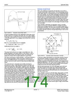
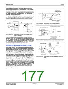
Load
Q2008L4
Triac
51 k
120 V ac
BS08D
(4) IN4004
0.02 µF
+
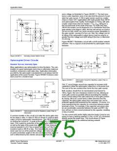
Figure AN1007.7 illustrates a circuit with a dv/dt snubber network
included. This is a typical circuit presented by optocoupler manu-
facturers.
PS2502
Hot
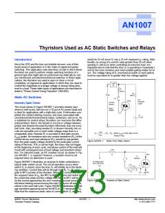
Figure AN1007.5
Normally Closed Switch Circuit
ZL
Optocoupled Driver Circuits
1
2
6
4
100
100
G
Rin
120 V
60 Hz
VCC
MT2
MT1
Random Turn-on, Normally Open
0.1 µF
C1
Many applications use optocouplers to drive thyristors. The com-
bination of a good optocoupler and a triac or alternistor makes an
excellent, inexpensive solid state relay. Application information
provided by the optocoupler manufacturers is not always best for
application of the power thyristor. Figure AN1007.6 shows a stan-
dard circuit for a resistive load.
Neutral
Figure AN1007.7
Optocoupler Circuit for Inductive Loads (Triac or
Alternistor)
Hot
This “T” circuit hinges around one capacitor to increase dv/dt
capability to either the optocoupler output triac or the power triac.
The sum of the two resistors then forms the triac gate resistor.
R
L
1
2
Both resistors should then be standardized and lowered to
100 Ω. Again, this sum resistance needs to be low, allowing as
much gate current as possible without exceeding the instanta-
neous current rating of the opto output triac or triac gate junction.
By having 100 Ω for current limit in either direction from the
capacitor, the optocoupler output triac and power triac can be
protected against di/dt produced by the capacitor. Of course, it is
most important that the capacitor be connected between proper
terminals of triac. For example, if the capacitor and series resis-
tor are accidentally connected between the gate and MT2, the
triac will turn on from current produced by the capacitor, resulting
in loss of control.
120 V
60 Hz
R
in
6
4
180
V
CC
MT2
MT1
G
Neutral
Load Could Be
in Either Leg
Figure AN1007.6
Optocoupled Circuit for Resistive Loads (Triac or
Alternistor)
For low current (mA) and/or highly inductive loads, it may be nec-
essary to have a latching network (3.3 kΩ + 0.047 µF) connected
directly across the power triac. The circuit shown in Figure
AN1007.8 illustrates the additional latching network.
A common mistake in this circuit is to make the series gate resis-
tor too large in value. A value of 180 Ω is shown in a typical appli-
cation circuit by optocoupler manufacturers. The 180 Ω is based
on limiting the current to 1 A peak at the peak of a 120 V line
input. This is good for protection of the optocoupler output triac,
as well as the gate of the power triac on a 120 V line; however, it
must be lowered if a 24 V line is being controlled, or if the RL
(resistive load) is 200 W or less. This resistor limits current for
worst case turn-on at the peak line voltage, but it also sets turn-
on point (conduction angle) in the sine wave, since triac gate cur-
rent is determined by this resistor and produced from the sine
©2002 Teccor Electronics
Thyristor Product Catalog
AN1007 - 3
http://www.teccor.com
+1 972-580-7777

 TECCOR [ TECCOR ELECTRONICS ]