AN1007
Application Notes
Normally Closed Circuit
With a few additional components, the thyristor can provide a
normally closed static switch function. The critical design portion
of this static switch is a clamping device to turn off/eliminate gate
drive and maintain very low power dissipation through the clamp-
ing component plus have low by-pass leakage around the power
thyristor device. In selecting the power thyristor for load require-
ments, gate sensitivity becomes critical to maintain low power
requirements. Either sensitive SCRs or sensitive logic triacs must
be considered, which limits the load in current capacity and type.
However, this can be broader if an extra stage of circuitry for gat-
ing is permitted.
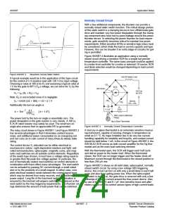
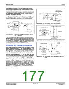
120 V rms (170 V peak)
VP+
VT+
≅1 V rms or 1.6 V peak MAX
θ
VT
-
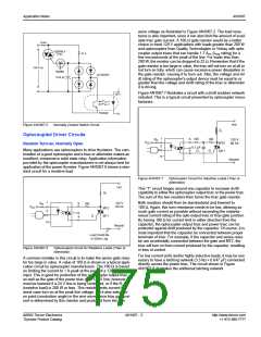
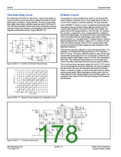
Figure AN1007.4 illustrates an application using a normally
closed circuit driving a sensitive SCR for a simple but precise
temperature controller. The same basic principle could be applied
to a water level controller for a motor or solenoid. Of course, SCR
and diode selection would be changed depending on load current
requirements.
VP
-
Figure AN1007.3
Waveform Across Static Switch
1000 W Heater Load
A typical example would be in the application of this type circuit
for the control of 5 A resistive load with 120 V rms input voltage.
Choosing a value of 100 Ω for R1 and assuming a typical value of
1 V for the gate to MT1 (VGT) voltage, we can solve for VP by the
following:
CR1
CR2
SCR1
S2010LS2
120 V ac
60 CPS
VP = IGT (RL + R1) + VGT
Note: RC is not included since it is negligible.
VP = 0.025 (24 + 100) + 1.0 = 4.1 V
Additionally the turn-on angle is
CR3
D2015L
CR1—CR4
CR4
R1
0.1 µF
510 k
–1
θ = Sin ---------------------
170V
4.1
[ θ = 1.4°]
PK
Twist Leads to Minimize
Pickup
The power lost by the turn-on angle is essentially zero. The
power dissipation in the gate resistor is very minute. A 100 Ω,
0.25 W rated resistor may safely be used. The small turn-on
angle also ensures that no appreciable RFI is generated.
Hg in Glass Thermostat
Figure AN1007.4
Normally Closed Temperature Controller
A mercury-in-glass thermostat is an extremely sensitive measur-
ing instrument, capable of sensing changes in temperature as
small as 0.1 °C. Its major limitation lies in its very low current-
handling capability for reliability and long life, and contact current
should be held below 1 mA. In the circuit of Figure AN1007.4, the
S2010LS2 SCR serves as both current amplifier for the Hg ther-
mostat and as the main load switching element.
With the thermostat open, the SCR will trigger each half cycle
and deliver power to the heater load. When the thermostat
closes, the SCR can no longer trigger and the heater shuts off.
Maximum current through the thermostat in the closed position is
less than 250 µA rms.
Figure AN1007.5 shows an all solid state, optocoupled, normally
closed switch circuit. By using a low voltage SBS triggering
device, this circuit can turn on with only a small delay in each half
cycle and also keep gating power low. When the optocoupled
transistor is turned on, the gate drive is removed with only a few
milliamps of bypass current around the triac power device. Also,
by use of the BS08D and 0.1 µF, less sensitive triacs and alter-
nistors can be used to control various types of high current loads.
The relay circuit shown in Figure AN1007.1 and Figure AN1007.2
has several advantages in that it eliminates contact bounce,
noise, and additional power consumption by an energizing coil
and can carry an in-rush current of many times its steady state
rating.
The control device S1 indicated can be either electrical or
mechanical in nature. Light-dependent resistors and light- acti-
vated semiconductors, optocoupler, magnetic cores, and mag-
netic reed switches are all suitable control elements. Regardless
of the switch type chosen, it must have a voltage rating equal to
or greater than the peak line voltage applied. In particular, the
use of hermetically sealed reed switches as control elements in
combination with triacs offers many advantages. The reed switch
can be actuated by passing DC current through a small coiled
wire or by the proximity of a small magnet. In either case, com-
plete electrical isolation exists between the control signal input,
which may be derived from many sources, and the switched
power output. Long life of the triac/reed switch combination is
ensured by the minimal volt-ampere switching load placed on the
reed switch by the triac triggering requirements. The thyristor rat-
ings determine the amount of load power that can be switched.
http://www.teccor.com
+1 972-580-7777
AN1007 - 2
©2002 Teccor Electronics
Thyristor Product Catalog

 TECCOR [ TECCOR ELECTRONICS ]