AN1007
7
Thyristors Used as AC Static Switches and Relays
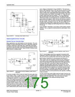
would be 25 mA since Q1 has a 25 mA maximum IGT rating. Addi-
tionally, no arcing of a current value greater than 25 mA when
Introduction
Since the SCR and the triac are bistable devices, one of their
broad areas of application is in the realm of signal and power
switching. This application note describes circuits in which these
thyristors are used to perform simple switching functions of a
general type that might also be performed non-statically by vari-
ous mechanical and electromechanical switches. In these appli-
cations, the thyristors are used to open or close a circuit
completely, as opposed to applications in which they are used to
control the magnitude of average voltage or energy being deliv-
ered to a load. These latter types of applications are described in
detail in “Phase Control Using Thyristors” (AN1003).
opening S1 will occur when controlling an inductive load. It is
important also to note that the triac Q1 is operating in Quadrants I
and III, the more sensitive and most suitable gating modes for tri-
acs. The voltage rating of S1 (mechanical switch or reed switch)
must be equivalent to or greater than line voltage applied.
Load
RL
R1
100 Ω
R2
100 Ω
VRMS
Static AC Switches
S1
For
Inductive
Loads
Triac
Control
Normally Open Circuit
Device
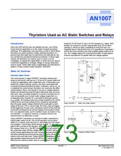
The circuit shown in Figure AN1007.1 provides random (any-
where in half-cycle), fast turn-on (<10 µs) of AC power loads and
is ideal for applications with a high-duty cycle. It eliminates com-
pletely the contact sticking, bounce, and wear associated with
conventional electromechanical relays, contactors, and so on. As
a substitute for control relays, thyristors can overcome the differ-
ential problem; that is, the spread in current or voltage between
pickup and dropout because thyristors effectively drop out every
half cycle. Also, providing resistor R1 is chosen correctly, the cir-
cuits are operable over a much wider voltage range than is a
comparable relay. Resistor R1 is provided to limit gate current
(IGTM) peaks. Its resistance plus any contact resistance (RC) of the
control device and load resistance (RL) should be just greater
than the peak supply voltage divided by the peak gate current
rating of the triac. If R1 is set too high, the triacs may not trigger
at the beginning of each cycle, and phase control of the load will
result with consequent loss of load voltage and waveform distor-
tion. For inductive loads, an RC snubber circuit, as shown in Fig-
ure AN1007.1, is required. However, a snubber circuit is not
required when an alternistor is used.
Reed
Switch
C1
0.1 µF
√2•V
IGTM
(RL + RC) Where IGTM is Peak Gate Current
Rating of Triac
R1
≥
Figure AN1007.1
Basic Triac Static Switch
Load
RL
MT2
Q1
Q2008L4
S1
AC Voltage Input
120 V rms, 60 Hz
Figure AN1007.2 illustrates an analysis to better understand a
typical static switch circuit. The circuit operation occurs when
switch S1 is closed, since the triac Q1 will initially be in the block-
ing condition. Current flow will be through load RL, S1, R1, and
gate to MT1 junction of the thyristor. When this current reaches
the required value of IGT, the MT2 to MT1 junctions will switch to
the conduction state and the voltage from MT2 to MT1 will be VT.
As the current approaches the zero crossing, the load current will
fall below holding current turning the triac Q1 device off until it is
refired in the next half cycle. Figure AN1007.3 illustrates the volt-
age waveform appearing across the MT2 to MT1 terminals of Q1.
Note that the maximum peak value of current which S1 will carry
I
I
+
GT
GT
G
VIN
R1
-
VGT
MT1
Figure AN1007.2
Analysis of Static Switch
©2002 Teccor Electronics
Thyristor Product Catalog
AN1007 - 1
http://www.teccor.com
+1 972-580-7777

 TECCOR [ TECCOR ELECTRONICS ]