STM32F405xx, STM32F407xx
Electrical characteristics
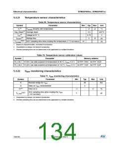
5.3.23
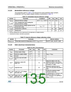
Embedded reference voltage
The parameters given in Table 72 are derived from tests performed under ambient
temperature and V supply voltage conditions summarized in Table 14.
DD
Table 72. Embedded internal reference voltage
Symbol
VREFINT
Parameter
Conditions
Min
Typ
Max
Unit
Internal reference voltage
–40 °C < TA < +105 °C 1.18 1.21 1.24
V
ADC sampling time when reading the
internal reference voltage
(1)
TS_vrefint
10
-
-
-
µs
Internal reference voltage spread over the
temperature range
(2)
VRERINT_s
VDD = 3 V
3
5
mV
(2)
TCoeff
Temperature coefficient
Startup time
-
-
30
6
50
10
ppm/°C
µs
(2)
tSTART
1. Shortest sampling time can be determined in the application by multiple iterations.
2. Guaranteed by design, not tested in production.
Table 73. Internal reference voltage calibration values
Parameter
Symbol
Memory address
VREFIN_CAL
Raw data acquired at temperature of 30 °C, VDDA=3.3 V
0x1FFF 7A2A - 0x1FFF 7A2B
5.3.24
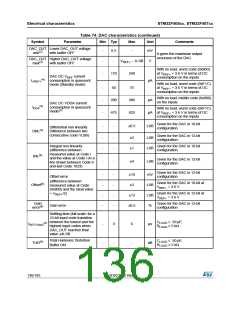
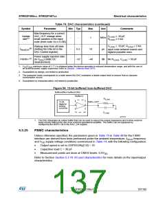
DAC electrical characteristics
Table 74. DAC characteristics
Symbol
Parameter
Min Typ
Max
Unit
Comments
VDDA
Analog supply voltage
1.8(1)
-
3.6
V
VREF+
VSSA
Reference supply voltage
Ground
1.8(1)
0
-
-
3.6
0
V
V
VREF+ ≤ VDDA
Resistive load with buffer
ON
(2)
RLOAD
5
-
-
kΩ
When the buffer is OFF, the
Minimum resistive load between
DAC_OUT and VSS to have a 1%
accuracy is 1.5 MΩ
Impedance output with
buffer OFF
(2)
RO
-
-
15
kΩ
Maximum capacitive load at
pF DAC_OUT pin (when the buffer is
ON).
(2)
CLOAD
Capacitive load
-
-
50
It gives the maximum output
excursion of the DAC.
DAC_OUT Lower DAC_OUT voltage
min(2)
with buffer ON
0.2
-
-
-
-
V
It corresponds to 12-bit input code
(0x0E0) to (0xF1C) at VREF+
3.6 V and (0x1C7) to (0xE38) at
VREF+ = 1.8 V
=
DAC_OUT Higher DAC_OUT voltage
max(2)
with buffer ON
V
DDA – 0.2
V
DocID022152 Rev 4
135/185

 STMICROELECTRONICS [ ST ]