STM32F405xx, STM32F407xx
Electrical characteristics
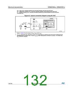
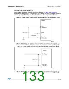
General PCB design guidelines
Power supply decoupling should be performed as shown in Figure 52 or Figure 53,
depending on whether V is connected to V or not. The 10 nF capacitors should be
REF+
DDA
ceramic (good quality). They should be placed them as close as possible to the chip.
Figure 52. Power supply and reference decoupling (V
not connected to V
)
DDA
REF+
STM32F
V
REF+
(See note 1)
1 µF // 10 nF
V
V
DDA
1 µF // 10 nF
/V
SSA REF-
(See note 1)
ai17535
1. VREF+ and VREF– inputs are both available on UFBGA176. VREF+ is also available on LQFP100, LQFP144,
and LQFP176. When VREF+ and VREF– are not available, they are internally connected to VDDA and VSSA
.
Figure 53. Power supply and reference decoupling (V
connected to V
)
DDA
REF+
STM32F
V
/V
REF+ DDA
(See note 1)
1 µF // 10 nF
V
/V
REF– SSA
(See note 1)
ai17536
1. VREF+ and VREF– inputs are both available on UFBGA176. VREF+ is also available on LQFP100, LQFP144,
and LQFP176. When VREF+ and VREF– are not available, they are internally connected to VDDA and VSSA
.
DocID022152 Rev 4
133/185

 STMICROELECTRONICS [ ST ]