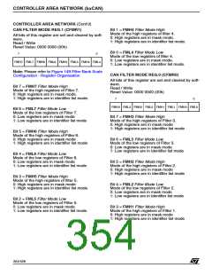
CONTROLLER AREA NETWORK (bxCAN)
CONTROLLER AREA NETWORK (Cont’d)
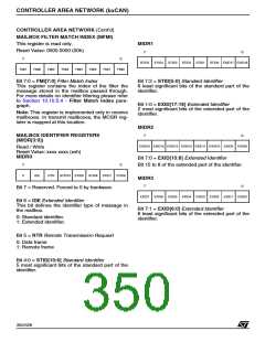
MAILBOX FILTER MATCH INDEX (MFMI)
This register is read only.
MIDR1
Reset Value: 0000 0000 (00h)
7
0
7
0
STID5
STID4
STID3
STID2
STID1
STID0 EXID17 EXID16
FMI7
FMI6
FMI5
FMI4
FMI3
FMI2
FMI1
FMI0
Bit 7:0 = FMI[7:0] Filter Match Index
Bit 7:2 = STID[5:0] Standard Identifier
6 least significant bits of the standard part of the
identifier.
This register contains the index of the filter the
message stored in the mailbox passed through.
For more details on identifier filtering please refer
to Section 10.10.5.4 - Filter Match Index para-
graph.
Bit 1:0 = EXID[17:16] Extended Identifier
2 most significant bits of the extended part of the
identifier.
Note: This register is implemented only in receive
mailboxes. In transmit mailboxes, the MCSR reg-
ister is mapped at this location.
MIDR2
7
0
MAILBOX IDENTIFIER REGISTERS
(MIDR[3:0])
EXID15 EXID14 EXID13 EXID12 EXID11 EXID10 EXID9
EXID8
Read / Write
Reset Value: xxxx xxxx (xxh)
MIDR0
Bit 7:0 = EXID[15:8] Extended Identifier
7
0
Bit 15 to 8 of the extended part of the identifier.
0
IDE
RTR
STID10 STID9
STID8
STID7
STID6
MIDR3
7
0
Bit 7 = Reserved. Forced to 0 by hardware.
EXID7
EXID6
EXID5
EXID4
EXID3
EXID2
EXID1
EXID0
Bit 6 = IDE Extended Identifier
This bit defines the identifier type of message in
the mailbox.
Bit 7:1 = EXID[6:0] Extended Identifier
6 least significant bits of the extended part of the
identifier.
0: Standard identifier.
1: Extended identifier.
Bit 5 = RTR Remote Transmission Request
0: Data frame
1: Remote frame
Bit 4:0 = STID[10:6] Standard Identifier
5 most significant bits of the standard part of the
identifier.
350/426
9

 STMICROELECTRONICS [ ST ]