CONTROLLER AREA NETWORK (bxCAN)
CONTROLLER AREA NETWORK (Cont’d)
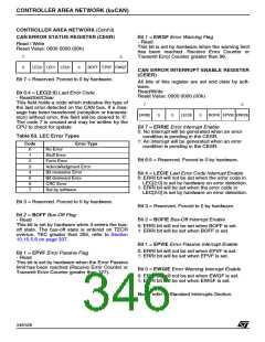
CAN ERROR STATUS REGISTER (CESR)
Bit 1 = EWGF Error Warning Flag
- Read
This bit is set by hardware when the warning limit
has been reached. Receive Error Counter or
Transmit Error Counter greater than 96.
Read / Write
Reset Value: 0000 0000 (00h)
7
0
0
LEC2 LEC1 LEC0
0
BOFF EPVF EWGF
CAN ERROR INTERRUPT ENABLE REGISTER
(CEIER)
Bit 7 = Reserved. Forced to 0 by hardware.
All bits of this register are set and clear by soft-
ware.
Read/Write
Reset Value: 0000 0000 (00h)
Bit 6:4 = LEC[2:0] Last Error Code
- Read/Set/Clear
This field holds a code which indicates the type of
the last error detected on the CAN bus. If a mes-
sage has been transferred (reception or transmis-
sion) without error, this field will be cleared to ‘0’.
The code 7 is unused and may be written by the
CPU to check for update
7
0
ERRIE
0
0
LECIE
0
BOFIE EPVIE EWGIE
Bit 7 = ERRIE Error Interrupt Enable
0: No interrupt will be generated when an error
condition is pending in the CESR.
Table 63. LEC Error Types
1: An interrupt will be generated when an error
condition is pending in the CESR.
Code
Error Type
0
1
2
3
4
5
6
7
No Error
Stuff Error
Form Error
Bit 6:5 = Reserved. Forced to 0 by hardware.
Acknowledgment Error
Bit recessive Error
Bit dominant Error
CRC Error
Bit 4 = LECIE Last Error Code Interrupt Enable
0: ERRI bit will not be set when the error code in
LEC[2:0] is set by hardware on error detection.
1: ERRI bit will be set when the error code in
LEC[2:0] is set by hardware on error detection.
Set by software
Bit 3 = Reserved. Forced to 0 by hardware.
Bit 3 = Reserved. Forced to 0 by hardware.
Bit 2 = BOFF Bus-Off Flag
- Read
Bit 2 = BOFIE Bus-Off Interrupt Enable
This bit is set by hardware when it enters the bus-
off state. The bus-off state is entered on TECR
overrun, TEC greater than 255, refer to Section
10.10.5.6 on page 337.
0: ERRI bit will not be set when BOFF is set.
1: ERRI bit will be set when BOFF is set.
Bit 1 = EPVIE Error Passive Interrupt Enable
0: ERRI bit will not be set when EPVF is set.
1: ERRI bit will be set when EPVF is set.
Bit 1 = EPVF Error Passive Flag
- Read
This bit is set by hardware when the Error Passive
limit has been reached (Receive Error Counter or
Transmit Error Counter greater than 127).
Bit 0 = EWGIE Error Warning Interrupt Enable
0: ERRI bit will not be set when EWGF is set.
1: ERRI bit will be set when EWGF is set.
Note: refer to Standard Interrupts Section.
346/426
9

 STMICROELECTRONICS [ ST ]