J1850 Byte Level Protocol Decoder (JBLPD)
J1850 BYTE LEVEL PROTOCOL DECODER (Cont’d)
10.9.5 Interrupt Features
– The RDRF interrupt is generated when a com-
plete data byte has been received and placed in
the RXDATA register (see also the RDRF bit
description of the STATUS register).
The JBLPD has six interrupt sources that it han-
dles using the internal interrupts protocol. Other
two interrupt sources (REOB and TEOB) are relat-
ed to the DMA feature (See Section 10.9.6 DMA
Features).
No external interrupt channel is used by the
JBLPD.
– The REOB (Receive End Of Block) interrupt is
generated when receiving using DMA and the
last byte of a sequence of data is read from the
JBLPD.
The dedicated registers of the JBLPD should be
loaded with appropriate values to set the interrupt
vector (see the description of the IVR register), the
interrupt mask bits (see the description of the IMR
register) and the interrupt pending bits (see the de-
scription of the STATUS and PRLR registers).
– The TRDY interrupt is generated by two condi-
tions: when the TXOP register is ready to ac-
cept a new opcode for transmission; when the
transmit state machine accepts the opcode for
transmission (a more detailed description of this
condition is given in the TRDY bit description of
the STATUS register).
The interrupt sources are as follows:
– The TEOB (Transmit End Of Block) interrupt is
generated when transmitting using DMA and
the last byte of a sequence of data is written to
the JBLPD.
– The ERROR interrupt is generated when the ER-
ROR bit of the STATUS register is set. This bit
is set when the following events occur: Trans-
mitter Timeout, Transmitter Data Underflow,
Receiver Data Overflow, Transmit Request
Aborted, Received Break Symbol, Cyclic Re-
dundancy Check Error, Invalid Frame Detect,
Invalid Bit Detect (a more detailed description of
these events is given in the description of the
ERROR register).
10.9.5.1 Interrupt Management
To use the interrupt features the user has to follow
these steps:
– Set the correct priority level of the JBLPD
– Set the correct interrupt vector
– Reset the Pending bits
– The TLA interrupt is generated when the trans-
mitter loses the arbitration (a more detailed de-
scription of this condition is given in the TLA bit
description of the STATUS register).
– Enable the required interrupt source
Note: It is strongly recommended to reset the
pending bits before un-masking the related inter-
rupt sources to avoid spurious interrupt requests.
– The EODM interrupt is generated when the
JBLPD detects a passive level on the VPWI line
longer than the minimum time accepted by the
standard for the End Of Data symbol (a more
detailed description of this condition is given in
the EODM bit description of the STATUS regis-
ter).
The priority with respect the other ST9 peripherals
is programmable by the user setting the three
most significant bits of the Interrupt Priority Level
register (PRLR). The lowest interrupt priority is ob-
tained by setting all the bits (this priority level is
never acknowledged by the CPU and is equivalent
to disabling the interrupts of the JBLPD); the high-
est interrupt priority is programmed resetting the
bits. See the Interrupt and DMA chapters of the
datasheet for more details.
– The EOFM interrupt is generated when the
JBLPD detects a passive level on the VPWI line
longer than the minimum time accepted by the
standard for the End Of Frame symbol (a more
detailed description of this condition is given in
the EOFM bit description of the STATUS regis-
ter).
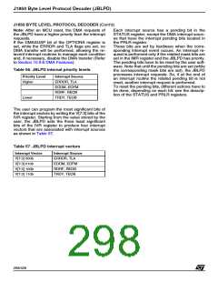
When the JBLPD interrupt priority is set, the prior-
ity between the internal interrupt sources is fixed
by hardware as shown in Table 56.
297/426
9

 STMICROELECTRONICS [ ST ]