J1850 Byte Level Protocol Decoder (JBLPD)
J1850 BYTE LEVEL PROTOCOL DECODER (Cont’d)
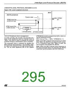
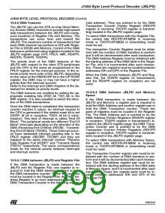
Figure 138. Local Loopback structure
MCU
JBLPD peripheral
Passive state
MCU VPWO
pin
VPWO from the
peripheral logic
VPWI toward the
J1850 decoder
Polarity
manager
MCU VPWI
pin
OPTIONS.INPOL
OPTIONS.LOOPB
10.9.3.8 Peripheral clock management
(FREQ[5:0]) must be programmed with a value us-
ing the following formula:
To work correctly, the encoder and decoder sec-
tions of the peripheral need an internal clock at
1MHz. This clock is used to evaluate the protocol
symbols timings in transmission and in reception.
MCU Internal Freq. = 1MHz * (FREQ[5:0] + 1).
Note: If the MCU internal clock frequency is lower
than 1MHz, the JBLPD is not able to work correct-
ly. If a frequency lower than 1MHz is used, the
user program must disable the JBLPD.
The prescaled clock is obtained by dividing the
MCU internal clock frequency. The CLKSEL regis-
ter allows the selection of the right prescaling fac-
tor. The six least significant bits of the register
Note: When the MCU internal clock frequency or
the clock prescaler factor are changed, the JBLPD
could lose synchronization with the J1850 bus.
295/426
9

 STMICROELECTRONICS [ ST ]