I2C BUS INTERFACE
2
I C BUS INTERFACE (Cont’d)
Next, depending on the data direction bit (least
significant bit of the address byte), and after the
generation of an acknowledge, the slave must go
in sending or receiving mode.
– AF: Detection of a no-acknowledge bit.
The I2CSR2.AF flag is set and an interrupt is
generated if the I2CCR.ITE bit is set.
Note: In both cases, SCL line is not stretched low;
however, the SDA line, due to possible «0» bits
transmitted last, can remain low. It is then neces-
sary to release both lines by software.
In 10-bit mode, after receiving the address se-
quence the slave is always in receive mode. It will
enter transmit mode on receiving a repeated Start
condition followed by the header sequence with
matching address bits and the least significant bit
set (11110xx1).
Other Events
– ADSL: Detection of a Start condition after an ac-
knowledge time-slot.
The state machine is reset and starts a new proc-
ess. The I2CSR1.ADSL flag bit is set and an in-
terrupt is generated if the I2CCR.ITE bit is set.
The SCL line is stretched low.
Slave Receiver
Following the address reception and after I2CSR1
register has been read, the slave receives bytes
from the SDA line into the Shift Register and sends
them to the I2CDR register. After each byte it
generates an acknowledge bit if the I2CCR.ACK
bit is set.
– STOPF: Detection of a Stop condition after an
acknowledge time-slot.
The state machine is reset. Then the
I2CSR2.STOPF flag is set and an interrupt is
generated if the I2CCR.ITE bit is set.
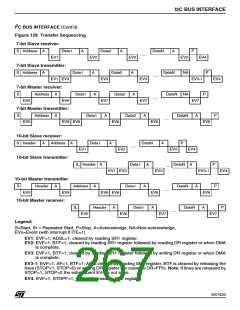
When the acknowledge bit is sent, the
I2CSR1.BTF flag is set and an interrupt is generat-
ed if the I2CCR.ITE bit is set (see Figure 128
Transfer sequencing EV2).
Then the interface waits for a read of the I2CSR1
register followed by a read of the I2CDR register,
or waits for the DMA to complete.
How to release the SDA / SCL lines
Check that the I2CSR1.BUSY bit is reset. Set and
subsequently clear the I2CCR.STOP bit while the
I2CSR1.BTF bit is set; then the SDA/SCL lines are
released immediately after the transfer of the cur-
rent byte.
Slave Transmitter
Following the address reception and after I2CSR1
register has been read, the slave sends bytes from
the I2CDR register to the SDA line via the internal
shift register.
This will also reset the state machine; any subse-
quent STOP bit (EV4) will not be detected.
2
10.8.4.2 I C Master Mode
When the acknowledge bit is received, the
I2CCR.BTF flag is set and an interrupt is
generated if the I2CCR.ITE bit is set (see Figure
128 Transfer sequencing EV3).
The slave waits for a read of the I2CSR1 register
followed by a write in the I2CDR register or waits
for the DMA to complete, both holding the SCL
line low (except on EV3-1).
To switch from default Slave mode to Master
mode a Start condition generation is needed.
Setting the I2CCR.START bit while the
I2CSR1.BUSY bit is cleared causes the interface
to generate a Start condition.
Once the Start condition is generated, the periph-
eral is in master mode (I2CSR1.M/SL=1) and
I2CSR1.SB (Start bit) flag is set and an interrupt is
generated if the I2CCR.ITE bit is set (see Figure
128 Transfer sequencing EV5 event).
Error Cases
– BERR: Detection of a Stop or a Start condition
during a byte transfer.
The I2CSR2.BERR flag is set and an interrupt is
generated if I2CCR.ITE bit is set.
The interface waits for a read of the I2CSR1 regis-
ter followed by a write in the I2CDR register with
the Slave address, holding the SCL line low.
If it is a stop then the state machine is reset.
If it is a start then the state machine is reset and
it waits for the new slave address on the bus.
265/426
9

 STMICROELECTRONICS [ ST ]