I2C BUS INTERFACE
2
I C BUS INTERFACE (Cont’d)
10.8.5 Interrupt Features
(I2CSR2.STOPF and I2CSR1.EVF flags = 1)
2
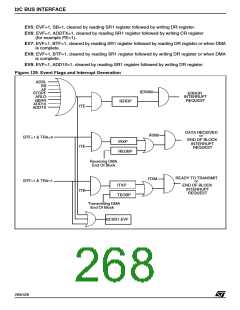
The I Cbus interface has three interrupt sources
related to “Error Condition”, “Peripheral Ready to
Transmit” and “Data Received”.
– Arbitration lost in Master mode
(I2CSR2.ARLO and I2CSR1.EVF flags = 1)
– Bus error, Start or Stop condition detected
during data transfer
(I2CSR2.BERR and I2CSR1.EVF flags = 1)
The peripheral uses the ST9+ interrupt internal
protocol without requiring the use of the external
interrupt channel. Dedicated registers of the pe-
ripheral should be loaded with appropriate values
to set the interrupt vector (see the description of
the I2CIVR register), the interrupt mask bits (see
the description of the I2CIMR register) and the in-
terrupt priority and pending bits (see the descrip-
tion of the I2CISR register).
The peripheral also has a global interrupt enable
(the I2CCR.ITE bit) that must be set to enable the
interrupt features. Moreover there is a global inter-
rupt flag (I2CSR1.EVF bit) which is set when one
of the interrupt events occurs (except the End Of
Block interrupts - see the DMA Features section).
– Master has sent the header byte
(I2CSR1.ADD10 and I2CSR1.EVF flags = 1)
– Address byte successfully transmitted in
Master mode.
(I2CSR1.EVF = 1 and I2CSR2.ADDTX=1)
Each interrupt source has a dedicated interrupt
address pointer vector stored in the I2CIVR regis-
ter. The five more significant bits of the vector ad-
dress are programmable by the customer, where-
as the three less significant bits are set by hard-
ware depending on the interrupt source:
– 010: error condition detected
– 100: data received
The “Data Received” interrupt source occurs after
the acknowledge of a received data byte is per-
formed. It is generated when the I2CSR1.BTF flag
is set and the I2CSR1.TRA flag is zero.
If the DMA feature is enabled in receiver mode,
this interrupt is not generated and the same inter-
rupt vector is used to send a Receiving End Of
Block interrupt (See the DMA feature section).
– 110: peripheral ready to transmit
The priority with respect to the other peripherals is
programmable by setting the PRL[2:0] bits in the
I2CISR register. The lowest interrupt priority is ob-
tained by setting all the bits (this priority level is
never acknowledged by the CPU and is equivalent
to disabling the interrupts of the peripheral); the
highest interrupt priority is programmed by reset-
ting all the bits. See the Interrupt and DMA chap-
ters for more details.
The “Peripheral Ready To Transmit” interrupt
source occurs as soon as a data byte can be
transmitted by the peripheral. It is generated when
the I2CSR1.BTF and the I2CSR1.TRA flags are
set.
If the DMA feature is enabled in transmitter mode,
this interrupt is not generated and the same inter-
rupt vector is used to send a Transmitting End Of
Block interrupt (See the DMA feature section).
The internal priority of the interrupt sources of the
peripheral is fixed by hardware with the following
order: “Error Condition” (highest priority), “Data
Received”, “Peripheral Ready to Transmit”.
Note: The DMA has the highest priority over the
interrupts; moreover the “Transmitting End Of
Block” interrupt has the same priority as the “Pe-
ripheral Ready to Transmit” interrupt and the “Re-
ceiving End Of Block” interrupt has the same prior-
ity as the “Data received” interrupt.
The “Error condition” interrupt source occurs when
one of the following condition occurs:
– Address matched in Slave mode while
I2CCR.ACK=1
(I2CSR1.ADSL and I2CSR1.EVF flags = 1)
Each of these three interrupt sources has a pend-
ing bit (IERRP, IRXP, ITXP) in the I2CISR register
that is set by hardware when the corresponding in-
terrupt event occurs. An interrupt request is per-
formed only if the corresponding mask bit is set
(IERRM, IRXM, ITXM) in the I2CIMR register and
the peripheral has a proper priority level.
– Start condition generated
(I2CSR1.SB and I2CSR1.EVF flags = 1)
– No acknowledge received after byte transmis-
sion
(I2CSR2.AF and I2CSR1.EVF flags = 1)
The pending bit has to be reset by software.
– Stop detected in Slave mode
269/426
9

 STMICROELECTRONICS [ ST ]