I2C BUS INTERFACE
2
I C BUS INTERFACE (Cont’d)
Then the slave address is sent to the SDA line.
In 7-bit addressing mode, one address byte is
sent.
In 10-bit addressing mode, sending the first byte
including the header sequence causes the
I2CSR1.EVF and I2CSR1.ADD10 bits to be set by
hardware with interrupt generation if the
I2CCR.ITE bit is set.
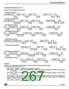
Then the master waits for a read of the I2CSR1
register followed by a write in the I2CDR register,
holding the SCL line low (see Figure 128 Trans-
fer sequencing EV9). Then the second address
byte is sent by the interface.
Note: In 10-bit addressing mode, to switch the
master to Receiver mode, software must generate
a repeated Start condition and resend the header
sequence with the least significant bit set
(11110xx1).
Master Receiver:
The master receives a byte from the SDA line into
the shift register and sends it to the I2CDR regis-
ter. It generates an acknowledge bit if the
I2CCR.ACK bit is set and an interrupt if the
I2CCR.ITE bit is set or a DMA is requested (see
Transfer sequencing EV7 event).
Then it waits for the microcontroller to read the
Data Register (I2CDR) or waits for the DMA to
complete both holding SCL line low.
After each address byte, an acknowledge clock
pulse is sent to the SCL line if the I2CSR1.EVF
and
– I2CSR1.ADD10 bit (if first header)
Error Cases
■ BERR: Detection of a Stop or a Start condition
during a byte transfer.
– I2CSR2.ADDTX bit (if address or second head-
er)
The I2CSR2.BERR flag is set and an interrupt is
generated if I2CCR.ITE is set.
are set, and an interrupt is generated if the
I2CCR.ITE bit is set.
■ AF: Detection of a no acknowledge bit
The I2CSR2.AF flag is set and an interrupt is
generated if I2CCR.ITE is set.
The peripheral waits for a read of the I2CSR1 reg-
ister followed by a write into the Control Register
(I2CCR) by holding the SCL line low (see Figure
128 Transfer sequencing EV6 event).
■ ARLO: Arbitration Lost
The I2CSR2.ARLO flag is set, the I2CSR1.M/SL
flag is cleared and the process is reset. An
interrupt is generated if the I2CCR.ITE bit is set.
If there was no acknowledge (I2CSR2.AF=1), the
master must stop or restart the communication
(set the I2CCR.START or I2CCR.STOP bits).
If there was an acknowledge, the state machine
enters a sending or receiving process according to
the data direction bit (least significant bit of the ad-
dress), the I2CSR1.BTF flag is set and an interrupt
is generated if I2CCR.ITE bit is set (see Transfer
sequencing EV7, EV8 events).
Note: In all cases, to resume communications, set
the I2CCR.START or I2CCR.STOP bits.
2
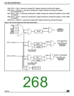
Events generated by the I C interface
■ STOP condition
When the I2CCR.STOP bit is set, a Stop
condition is generated after the transfer of the
current byte, the I2CSR1.M/SL flag is cleared
and the state machine is reset. No interrupt is
generated in master mode at the detection of
the stop condition.
If the master loses the arbitration of the bus there
is no acknowledge, the I2CSR2.AF flag is set and
the master must set the START or STOP bit in the
control register (I2CCR).The I2CSR2.ARLO flag is
set, the I2CSR1.M/SL flag is cleared and the proc-
ess is reset. An interrupt is generated if I2CCR.ITE
is set.
■ START condition
When the I2CCR.START bit is set, a start
2
condition is generated as soon as the I C bus is
Master Transmitter:
free. The I2CSR1.SB flag is set and an interrupt
is generated if the I2CCR.ITE bit is set.
The master waits for the microcontroller to write in
the Data Register (I2CDR) or it waits for the DMA
to complete both holding the SCL line low (see
Transfer sequencing EV8).
Then the byte is received into the shift register and
sent to the SDA line. When the acknowledge bit is
received, the I2CSR1.BTF flag is set and an
interrupt is generated if the I2CCR.ITE bit is set or
the DMA is requested.
266/426
9

 STMICROELECTRONICS [ ST ]