ST10F276E
Electrical characteristics
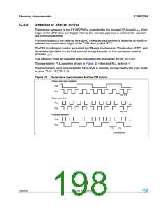
23.8.3
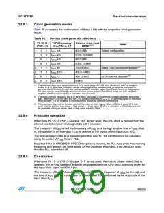
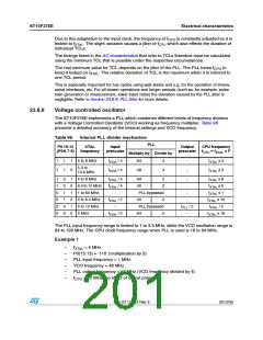
Clock generation modes
Table 95 associates the combinations of these 3 bits with the respective clock generation
mode.
Table 95. On-chip clock generator selections
P0.15-13
(P0H.7-5)
CPU frequency
CPU = fXTAL x F
External clock input
range(1)(2)
Notes
Default configuration
f
1
1
1
1
0
0
0
0
1
1
0
0
1
1
0
0
1
0
1
0
1
0
1
0
f
XTAL x 4
4 to 8 MHz
5.3 to 10.6 MHz
4 to 8 MHz
6.4 to 12 MHz
1 to 64 MHz
4 to 6.4 MHz
4 to 12 MHz
4 MHz
fXTAL x 3
f
f
XTAL x 8
XTAL x 5
fXTAL x 1
Direct Drive (oscillator bypassed)(3)
CPU clock via prescaler(3)
fXTAL x 10
f
XTAL / 2
fXTAL x 16
1. The external clock input range refers to a CPU clock range of 1...64 MHz. Moreover, the PLL usage is
limited to 4-12 MHz input frequency range. All configurations need a crystal (or ceramic resonator) to
generate the CPU clock through the internal oscillator amplifier (apart from Direct Drive); on the contrary,
the clock can be forced through an external clock source only in Direct Drive mode (on-chip oscillator
amplifier disabled, so no crystal or resonator can be used).
2. The limits on input frequency are 4-12 MHz since the usage of the internal oscillator amplifier is required.
Also, when the PLL is not used and the CPU clock corresponds to f
/2, an external crystal or resonator
XTAL
must be used: It is not possible to force any clock though an external clock source.
3. The maximum depends on the duty cycle of the external clock signal: When 64 MHz is used, 50% duty
cycle shall be granted (low phase = high phase = 7.8ns); when 32 MHz is selected, a 25% duty cycle can
be accepted (minimum phase, high or low, again equal to 7.8ns).
23.8.4
Prescaler operation
When pins P0.15-13 (P0H.7-5) equal ‘001’ during reset, the CPU clock is derived from the
internal oscillator (input clock signal) by a 2:1 prescaler.
The frequency of fCPU is half the frequency of fXTAL and the high and low time of fCPU (that
is, the duration of an individual TCL) is defined by the period of the input clock fXTAL
.
The timings listed in the AC Characteristics that refer to TCL can therefore be calculated
using the period of fXTAL for any TCL.
Note that if the bit OWDDIS in SYSCON register is cleared, the PLL runs on its free-running
frequency and delivers the clock signal for the Oscillator Watchdog. If bit OWDDIS is set,
then the PLL is switched off.
23.8.5
Direct drive
When pins P0.15-13 (P0H.7-5) equal ‘011’ during reset, the on-chip phase locked loop is
disabled, the on-chip oscillator amplifier is bypassed and the CPU clock is directly driven by
the input clock signal on XTAL1 pin.
The frequency of the CPU clock (fCPU) directly follows the frequency of fXTAL so the high and
low time of fCPU (that is, the duration of an individual TCL) is defined by the duty cycle of the
input clock fXTAL
.
Doc ID 12303 Rev 3
199/235

 STMICROELECTRONICS [ ST ]