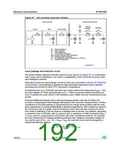
Electrical characteristics
ST10F276E
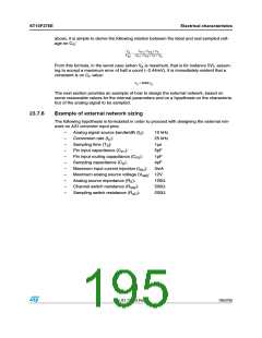
1. Supposing to design the filter with the pole exactly at the maximum frequency of the
signal, the time constant of the filter is:
1
2πf
-----------
R
C
=
F
= 15.9μs
C
0
2. Using the relation between CF and CS and taking some margin (4000 instead of 2048),
it is possible to define CF:
C
= 4000C⋅ = 16nF
S
F
3. As a consequence of Step 1 and 2, RC can be chosen:
1
-------------------
R
=
= 995Ω ≅ 1kΩ
F
2πf
C
F
0
4. Considering the current injection limitation and supposing that the source can go up to
12V, the total series resistance can be defined as:
V
AM
R
+ R
+
R
= ------------- = 4kΩ
S
F
L
I
INJ
5. from which is now simple to define the value of RL:
V
AM
R
= ------------- – R – R = 2.9kΩ
L
F
S
I
INJ
Now, the three elements of the external circuit RF, CF and RL are defined. Some conditions
discussed in the previous paragraphs have been used to size the component; the others
must now be verified. The relation which allows to minimize the accuracy error introduced by
the switched capacitance equivalent resistance is in this case:
1
R
= --------------= 10MΩ
EQ
f
C
C
S
So the error due to the voltage partitioning between the real resistive path and CS is less
then half a count (considering the worst case when VA = 5V):
R
+R +R +R
+R
1
2
S
F
L
SW
AD
------------------------------------------------------------------------
--
= 2.35mV < LSB
V
⋅
A
R
EQ
The other conditions to verify are if the time constants of the transients are really and
significantly shorter than the sampling period duration TS:
τ
= (R
+ R ) ⋅ C = 2.8ns
<< TS = 1μs
AD S
1
SW
10 τ⋅ = 10R⋅ (⋅C + C + C ) = 290ns < TS = 1μs
P1 P2
2
L
S
For a complete set of parameters characterizing the ST10F276E A/D converter equivalent
circuit, refer to Table 93: A/D converter characteristics on page 187.
196/235
Doc ID 12303 Rev 3

 STMICROELECTRONICS [ ST ]