powerSTEP01
Functional description
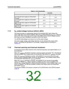
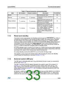
Table 9. Thermal protection summarizing table
State
Set condition
Release condition
Description
Normal operation state
TH_STATUS
Normal
00
Temperature warning: operation is
not limited
Warning
Tj > Tj(WRN)Set
Tj< Tj(WRN)Rel
01
10
High temperature protection: the
MOSFETs are turned off and the
gate drivers are disabled
Bridge shutdown
Tj > Tj(OFF)Set
Tj < Tj(OFF)Rel
Overtemperature protection: the
MOSFETs are turned off, the gate
drivers are disabled, the internal
VCC voltage regulator is disabled,
the current capability of the
internal VREG voltage regulator is
limited, and the charge pump is
disabled
Device shutdown
Tj > Tj(SD)Set
Tj < Tj(SD)Rel
11
7.13
Reset and standby
The device can be reset and put into Standby mode through the STBY/RESET pin. When it
is forced low, all the MOSFETs are turned off (High Z state), the charge pump is stopped,
the SPI interface and control logic are disabled and the internal VREG voltage regulator
maximum output current is limited; as a result, the powerSTEP01 heavily reduces the power
consumption. At the same time the register values are reset to their default and all the
protection functions are disabled. The STBY/RESET input must be forced low at least for
tSTBY,min in order to ensure the complete switch to Standby mode.
On exiting Standby mode, as well as for IC power-up, a delay must be given before applying
a new command to allow proper oscillator and charge pump startup. Actual delay could vary
according to the values of the charge pump external components.
On exiting Standby mode all the MOSFETs are off and the HiZ flag is high.
The registers can be reset to the default values without putting the device into Standby
mode through the ResetDevice command (Section 11.2.14).
7.14
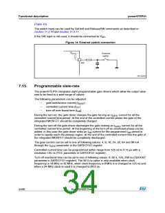
External switch (SW pin)
The SW input is internally pulled up to VDD and detects if the pin is open or connected to
ground (see Figure 14).
The SW_F bit of the STATUS register indicates if the switch is open (‘0’) or closed (‘1’)
(Section 11.1.28); the bit value is refreshed at every system clock cycle (125 ns). The
SW_EVN flag of the STATUS register is raised when a switch turn-on event (SW input
falling edge) is detected (Section 11.1.28). A GetStatus command releases the SW_EVN
flag (Section 11.2.20).
By default, a switch turn-on event causes a HardStop interrupt (SW_MODE bit of CONFIG
register set to ‘0’). Otherwise (SW_MODE bit of CONFIG register set to ‘1’), switch input
events do not cause interrupts and the switch status information is at the user’s disposal
DocID025022 Rev 1
33/90

 STMICROELECTRONICS [ ST ]